
User Service Guide, Third Edition - HP Integrity rx4640 Server
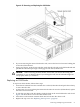
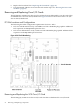
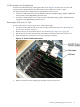
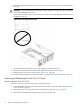
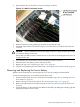

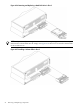
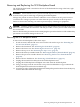
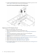
Table Of Contents
- HP Integrity rx4640 Server User Service Guide
- Table of Contents
- About This Document
- 1 Introduction
- 2 Controls, Ports, and LEDs
- 3 Powering Off and Powering On the Server
- 4 Removing and Replacing Components
- Safety Information
- Service Tools Required
- Accessing a Rack Mounted Server
- Accessing a Pedestal Mounted Server
- Removing and Replacing the Front Bezel
- Removing and Replacing the Front and Top Covers
- Removing and Replacing the Memory Extender Board
- Removing and Replacing Memory DIMMs
- Removing and Replacing the Processor Extender Board
- Removing and Replacing a Processor
- Removing and Replacing Hot-Swappable Chassis Fans
- Removing and Replacing the I/O Baseboard
- Removing and Replacing Hot-Pluggable PCI-X Cards
- Removing and Replacing OLX Dividers
- Removing and Replacing Core I/O Cards
- Removing and Replacing the Server Battery
- Removing and Replacing Hard Disk Drives
- Removing and Replacing the SCSI Backplane Board
- Removing and Replacing the Midplane Riser Board
- Removing and Replacing the Power Supplies
- Removing and Replacing the Power Distribution Board
- Removing and Replacing the DVD Drive
- Removing and Replacing the DVD I/O Board
- Removing and Replacing the Display Board
- Removing and Replacing the QuickFind Diagnostic Board
- 5 Troubleshooting
- Troubleshooting Tips
- Possible Problems
- Troubleshooting Using LED Indicators
- Diagnostics
- Recommended Cleaning Procedures
- Where to Get Help
- A Parts Information
- B Booting the Operating System
- Operating Systems Supported on HP Integrity Servers
- Configuring System Boot Options
- Booting and Shutting Down HP-UX
- Booting and Shutting Down HP OpenVMS
- Booting and Shutting Down Microsoft Windows
- Booting and Shutting Down Linux
- C Utilities
- Extensible Firmware Interface Boot Manager
- EFI/POSSE Commands
- Specifying SCSI Parameters
- Using the Boot Configuration Menu
- Index
4. Open the blue PCI card latch for slot 2 by twisting it clockwise.
Figure 4-33 LAN I/O Card Latch Location
5. Remove LAN I/O card by pulling up carefully on the LAN I/O card.
6. Install the replacement LAN I/O card. Figure 4-32 shows how to install the LAN I/O card
correctly.
CAUTION: Always handle I/O cards by their edges. Failure to comply with this precaution
can result in damage to the card.
Ensure that you fully seat the card into the slot or the card can be damaged when power is
reapplied to the slot.
7. Close the blue PCI card latch for slot 2 by twisting it counter-clockwise.
8. Reconnect the LAN cable(s) to the LAN core I/O card.
9. Replace the top cover. “Replacing the Top Cover” (page 36).
10. Push the server back into the rack until it stops. “Inserting the Server into the Rack” (page 32).
Removing and Replacing the Server Battery
Replace the server battery by removing the top cover and accessing the I/O baseboard.
To remove and replace the server battery, follow these steps:
1. If rack mounted, slide the server out from the rack until it stops. See “Extending the Server
From the Rack” (page 31).
2. Remove the top cover from the chassis. See “Removing the Top Cover” (page 36).
3. Remove the I/O baseboard assembly from the chassis. See “Removing the I/O Baseboard”
(page 56).
4. Locate the battery on the I/O baseboard. Remove the battery by lifting the retaining clip and
pulling the battery from its socket.
Removing and Replacing the Server Battery 75