
User Service Guide, Third Edition - HP Integrity rx4640 Server
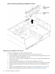

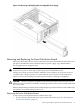
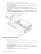
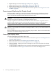
Table Of Contents
- HP Integrity rx4640 Server User Service Guide
- Table of Contents
- About This Document
- 1 Introduction
- 2 Controls, Ports, and LEDs
- 3 Powering Off and Powering On the Server
- 4 Removing and Replacing Components
- Safety Information
- Service Tools Required
- Accessing a Rack Mounted Server
- Accessing a Pedestal Mounted Server
- Removing and Replacing the Front Bezel
- Removing and Replacing the Front and Top Covers
- Removing and Replacing the Memory Extender Board
- Removing and Replacing Memory DIMMs
- Removing and Replacing the Processor Extender Board
- Removing and Replacing a Processor
- Removing and Replacing Hot-Swappable Chassis Fans
- Removing and Replacing the I/O Baseboard
- Removing and Replacing Hot-Pluggable PCI-X Cards
- Removing and Replacing OLX Dividers
- Removing and Replacing Core I/O Cards
- Removing and Replacing the Server Battery
- Removing and Replacing Hard Disk Drives
- Removing and Replacing the SCSI Backplane Board
- Removing and Replacing the Midplane Riser Board
- Removing and Replacing the Power Supplies
- Removing and Replacing the Power Distribution Board
- Removing and Replacing the DVD Drive
- Removing and Replacing the DVD I/O Board
- Removing and Replacing the Display Board
- Removing and Replacing the QuickFind Diagnostic Board
- 5 Troubleshooting
- Troubleshooting Tips
- Possible Problems
- Troubleshooting Using LED Indicators
- Diagnostics
- Recommended Cleaning Procedures
- Where to Get Help
- A Parts Information
- B Booting the Operating System
- Operating Systems Supported on HP Integrity Servers
- Configuring System Boot Options
- Booting and Shutting Down HP-UX
- Booting and Shutting Down HP OpenVMS
- Booting and Shutting Down Microsoft Windows
- Booting and Shutting Down Linux
- C Utilities
- Extensible Firmware Interface Boot Manager
- EFI/POSSE Commands
- Specifying SCSI Parameters
- Using the Boot Configuration Menu
- Index
2. Remove the top cover. See “Removing the Top Cover” (page 36).
3. Remove the power supply fan unit from the chassis. See “Removing a Hot-Swappable
Chassis Fan Unit” (page 53).
4. Remove the hot-swappable power supply from the chassis. See “Removing a Hot-Swappable
Power Supply” (page 84).
5. Unplug the power cable and the signal cable from the midplane riser board.
6. Using a torx #15 driver, loosen the one torx screw attaching the power distribution board
to the chassis.
7. Push the power distribution board towards the center of the chassis to release it from the
keyway slots. Pull it off the keyway slots and up and out of the chassis. Figure 4-41 shows
how to remove the power distribution board.
Figure 4-41 Removing and Replacing the Power Distribution Board
Replacing the Power Distribution Board
To replace the power distribution board, follow these steps:
1. Replace the power distribution board over the keyway slots and push it towards the side
of the chassis to lock it onto the studs.
2. Reattach the power distribution board to the chassis bulkhead by replacing the one torx #15
screw. Hand tighten the screw.
3. Plug the power and signal cables back into the midplane riser board.
4. Replace the hot-swappable power supply into the chassis. See “Replacing a Hot-Swappable
Power Supply” (page 84).
5. Replace the power supply fan unit into the chassis. See “Replacing a Hot-Swappable Chassis
Fan Unit” (page 55).
6. Replace the top cover. See “Replacing the Top Cover” (page 36).
86 Removing and Replacing Components