
User Service Guide, Third Edition - HP Integrity rx4640 Server
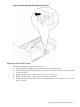
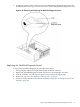

Table Of Contents
- HP Integrity rx4640 Server User Service Guide
- Table of Contents
- About This Document
- 1 Introduction
- 2 Controls, Ports, and LEDs
- 3 Powering Off and Powering On the Server
- 4 Removing and Replacing Components
- Safety Information
- Service Tools Required
- Accessing a Rack Mounted Server
- Accessing a Pedestal Mounted Server
- Removing and Replacing the Front Bezel
- Removing and Replacing the Front and Top Covers
- Removing and Replacing the Memory Extender Board
- Removing and Replacing Memory DIMMs
- Removing and Replacing the Processor Extender Board
- Removing and Replacing a Processor
- Removing and Replacing Hot-Swappable Chassis Fans
- Removing and Replacing the I/O Baseboard
- Removing and Replacing Hot-Pluggable PCI-X Cards
- Removing and Replacing OLX Dividers
- Removing and Replacing Core I/O Cards
- Removing and Replacing the Server Battery
- Removing and Replacing Hard Disk Drives
- Removing and Replacing the SCSI Backplane Board
- Removing and Replacing the Midplane Riser Board
- Removing and Replacing the Power Supplies
- Removing and Replacing the Power Distribution Board
- Removing and Replacing the DVD Drive
- Removing and Replacing the DVD I/O Board
- Removing and Replacing the Display Board
- Removing and Replacing the QuickFind Diagnostic Board
- 5 Troubleshooting
- Troubleshooting Tips
- Possible Problems
- Troubleshooting Using LED Indicators
- Diagnostics
- Recommended Cleaning Procedures
- Where to Get Help
- A Parts Information
- B Booting the Operating System
- Operating Systems Supported on HP Integrity Servers
- Configuring System Boot Options
- Booting and Shutting Down HP-UX
- Booting and Shutting Down HP OpenVMS
- Booting and Shutting Down Microsoft Windows
- Booting and Shutting Down Linux
- C Utilities
- Extensible Firmware Interface Boot Manager
- EFI/POSSE Commands
- Specifying SCSI Parameters
- Using the Boot Configuration Menu
- Index
5 Troubleshooting
This chapter provides troubleshooting instructions used in the installation of the HP Integrity
rx4640 server.
Troubleshooting Tips
WARNING! Before removing a cover to service components that cannot be hot-swapped, always
disconnect the AC power cords and unplug telephone cables. Disconnect telephone cables to
avoid exposure to shock hazard from telephone ringing voltages.
Disconnect the AC power cords to avoid exposure to high energy levels that can cause burns
when parts are short-circuited by metal objects such as tools or jewelry.
CAUTION: Do not operate the server for more than two minutes with any cover (including
power supplies and disk drives) removed. Damage to server components can result due to
improper cooling airflow.
However, you can safely remove a cover while the server is running to remove and replace PCI
hot-pluggable boards. For any other service activity requiring access to the I/O baseboard or
power distribution board, power off the server and observe all safety precautions.
Troubleshooting Methodology
1. This is the entry point to the troubleshooting process. Here, you pick from a set of symptoms,
ranging from very simple (server LED is blinking) to the most difficult (Machine Check
Abort [MCA]) has occurred. The following is a list of symptom examples:
• Server LED blinking
• System Alert present on console
• Server does not power-on
• Server does not boot
• Event/Error Message received
• Machine Check Abort (MCA)
2. This step narrows down the observed problem to the specific troubleshooting procedure
required. Here you isolate the failure to a specific part of the server so that you can perform
more detailed troubleshooting. For example:
• Problem-Server LED blinking
— System Alert on console?
— Analyze the alert by using the system event log (SEL) to identify the last error
logged by the baseboard management controller. Use the iLO MP commands to
view the SEL.
3. At this point you should have a good idea about which area of the server requires further
analysis. For example, if the symptom was “server does not power-on,” the initial
troubleshooting procedure could indicate a problem with the DC power supply not coming
up after the power switch was turned on.
4. You have now reached the point where the failed Field Replaceable Unit (FRU or FRUs)
have been identified and need to be replaced. You must now perform the specific
remove-and-replace verification steps.
Troubleshooting Tips 95