
User Service Guide, Third Edition - HP Integrity rx4640 Server
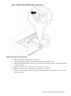
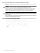
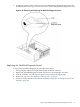

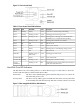
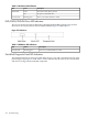
Table Of Contents
- HP Integrity rx4640 Server User Service Guide
- Table of Contents
- About This Document
- 1 Introduction
- 2 Controls, Ports, and LEDs
- 3 Powering Off and Powering On the Server
- 4 Removing and Replacing Components
- Safety Information
- Service Tools Required
- Accessing a Rack Mounted Server
- Accessing a Pedestal Mounted Server
- Removing and Replacing the Front Bezel
- Removing and Replacing the Front and Top Covers
- Removing and Replacing the Memory Extender Board
- Removing and Replacing Memory DIMMs
- Removing and Replacing the Processor Extender Board
- Removing and Replacing a Processor
- Removing and Replacing Hot-Swappable Chassis Fans
- Removing and Replacing the I/O Baseboard
- Removing and Replacing Hot-Pluggable PCI-X Cards
- Removing and Replacing OLX Dividers
- Removing and Replacing Core I/O Cards
- Removing and Replacing the Server Battery
- Removing and Replacing Hard Disk Drives
- Removing and Replacing the SCSI Backplane Board
- Removing and Replacing the Midplane Riser Board
- Removing and Replacing the Power Supplies
- Removing and Replacing the Power Distribution Board
- Removing and Replacing the DVD Drive
- Removing and Replacing the DVD I/O Board
- Removing and Replacing the Display Board
- Removing and Replacing the QuickFind Diagnostic Board
- 5 Troubleshooting
- Troubleshooting Tips
- Possible Problems
- Troubleshooting Using LED Indicators
- Diagnostics
- Recommended Cleaning Procedures
- Where to Get Help
- A Parts Information
- B Booting the Operating System
- Operating Systems Supported on HP Integrity Servers
- Configuring System Boot Options
- Booting and Shutting Down HP-UX
- Booting and Shutting Down HP OpenVMS
- Booting and Shutting Down Microsoft Windows
- Booting and Shutting Down Linux
- C Utilities
- Extensible Firmware Interface Boot Manager
- EFI/POSSE Commands
- Specifying SCSI Parameters
- Using the Boot Configuration Menu
- Index
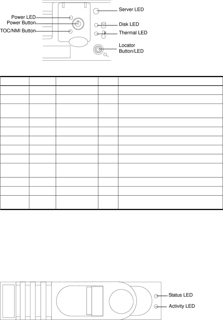
Figure 5-1 Front Control Panel
Table 5-1 Front Control Panel LED Definitions
DescriptionColorFlash RateStateLED/ Button
Green: Server normal-OS up and runningGreenSteadyRunningServer
Flashing green: OS booting or at EFIGreenFlashing at 0.5HzBootingServer
Flashing yellow: Warning-server needs attention.
Redundancy lost, component failure pending
YellowFlashing at 1 HzAttentionServer
Flashing red: hard fault, server haltedRedFlashing at 2 HzFaultServer
Off: server offN/AOffOffServer
Green: power normalGreenSteadyOnPower
Flashing yellow: Housekeeping voltage presentYellowSteadyOnPower
Off: Power offOffOffOffPower
Flashing green: disk activityGreenFlashing at rate of
disk activity
Disk LED
Green: thermal OKGreenSteadyOKThermal LED
Flashing yellow-thermal warningYellowFlashing at 1 HzWarningThermal LED
Flashing blue: server locator LED may be remotely or
locally activated/deactivated
BlueFlashing at 1 HzLocator
LED/Button
Hard Disk Drive LED Indicators
The disk drives have two LEDs per drive, as shown below. Figure 5-2 and Table 5-2 show the
location and description of the hard disk drive LEDs.
Status LED The drive status LED displays green when the disk power is on, and is off
when the disk power is off.
Activity LED The drive activity LED is green and indicates disk drive activity. This LED
is controlled by the disk drive directly and turns on when a drive is accessed.
Figure 5-2 Hot-swappable Disk Drive LED Indicators
Troubleshooting Using LED Indicators 99