CPU Installation Product Update Manufacturing Part Number: A6837-96004 July 2003 U.S.A. © Copyright 2003, Hewlett-Packard Development Company L.P. All rights reserved.
Warranty and Support Refer to the warranty statement provided with your original HP Server system documentation for the warranty limitations, customer responsibilities, and other terms and conditions. HP Repair and Telephone Support Refer to the Warranty & Support for your HP Server booklet supplied with your HP Server system documentation for instructions on how to obtain HP repair and telephone support. Related Documents. The HP Server Documentation CD-ROM has been provided with your server.
CPU Installation Important Steps 1 CPU Installation Problems have been encountered when installing CPU modules on processor extender boards in the field. The most common problem is bent processor pins, which can short out processor circuits. This notice emphasizes the proper method of CPU installation and cautions against potential errors. Read these instructions and use care to ensure a successful CPU installation.
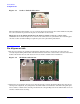
CPU Installation Pin Alignment Aids Figure 1-1 Socket - Unlocked Position camlocked When installing the CPU module, use care to insert all processor pins into the socket simultaneously. The two connectors must be parallel as the pins are inserted in to the sockets. When pins are bent during installation, the damage usually occurs at a corner of the connector. Do not allow the pins at one corner of the connectors to be joined before the remaining pins enter the socket.
CPU Installation Pin Alignment Aids Figure 1-3 CPU Guide Pins guidepins 3. When installing a CPU module, visually confirm that the CPU assembly is parallel to the processor extender board and that socket tabs mate with the corresponding cutouts in the processor connector.
CPU Installation Pin Alignment Aids 6 Chapter 1