hp Integrity rx5670 Hardware Installation Guide Product ID: A6837B/A6838B Manufacturing Part Number : A6837-96001 July 2003 USA © Copyright 2003 Hewlett-Packard Company.
Legal Notices The information in this document is subject to change without notice. Hewlett-Packard makes no warranty of any kind with regard to this guide, including, but not limited to, the implied warranties of merchantability and fitness for a particular purpose. Hewlett-Packard shall not be held liable for errors contained herein or direct, indirect, special, incidental or consequential damages in connection with the furnishing, performance, or use of this material. Restricted Rights Legend.
Contents 1. Server Overview and Unpacking Server Overview . . . . . . . . . . . . . . . . . . . . . . . . . . . . . . . . . . . . . . . . . . . . . . . . . . . . . . . . . . . . . . . . . . . . . . 5 Unpacking the Server . . . . . . . . . . . . . . . . . . . . . . . . . . . . . . . . . . . . . . . . . . . . . . . . . . . . . . . . . . . . . . . . 11 Unpacking a Racked Server . . . . . . . . . . . . . . . . . . . . . . . . . . . . . . . . . . . . . . . . . . . . . . . . . . . . . . . . . .
Contents MP/SCSI Connections. . . . . . . . . . . . . . . . . . . . . . . . . . . . . . . . . . . . . . . . . . . . . . . . . . . . . . . . . . . . . . . LAN/SCSI Connections . . . . . . . . . . . . . . . . . . . . . . . . . . . . . . . . . . . . . . . . . . . . . . . . . . . . . . . . . . . . . Management Processor. . . . . . . . . . . . . . . . . . . . . . . . . . . . . . . . . . . . . . . . . . . . . . . . . . . . . . . . . . . . . . Booting the Server . . . . . . . . . . . . . . . . . . . . . . . . . .
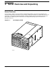
1 Server Overview and Unpacking Server Overview The hp Integrity rx5670 is a 4-way symmetric multiprocessing (SMP), rack-mount server based on the Itanium processor family architecture. The hp Integrity rx5670 accommodates up to 48 DIMMs and internal peripherals including disks and DVD ROM/Tape. Its high availability features include hot swap fans and power supplies, and hot plug internal disk drives. The supported operating systems include HP-UX, Windows, and Linux.
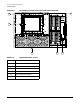
Server Overview and Unpacking Server Overview Figure 1-2 hp Integrity rx5670 (front view with bezel removed) B A F ever042 E Table 1-1 Identifier 6 D C Important Items - Front Component A Front panel LEDs B Power switch C Removable media drive D Hot plug disk drives E Hot swap power supplies F Front hot swap chassis fan cover Chapter 1
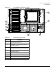
Server Overview and Unpacking Server Overview Figure 1-3 hp Integrity rx5670 (rear view) E F A B C D ever017 H Table 1-2 Identifier Important Items - Rear Component A NetRaid PCI card (optional, supported with Windows and Linux) B LAN/SCSI PCI card (required with all operating systems) C VGA/USB PCI card (required with Windows, optional for HP-UX and Linux) D MP/SCSI PCI card (required with all operating systems) E Rear hot swap chassis fan cover F Power receptacles G Power converter H
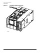
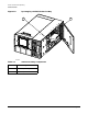
Server Overview and Unpacking Server Overview Figure 1-4 hp Integrity rx5670 Top Service Bay ever046 8 Chapter 1
Server Overview and Unpacking Server Overview Figure 1-5 hp Integrity rx5670 Top Service Bay Components A B D C ever038 Table 1-3 Identifier Top Service Bay Components Component A Processor extender board B Memory extender board MX0 (required) C System baseboard D Memory extender board MX1 (optional) Chapter 1 9
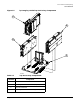
Server Overview and Unpacking Server Overview Figure 1-6 hp Integrity rx5670 Side Service Bay A 4x B ever016 Table 1-4 Identifier 10 Side Service Bay Components Component A Hot swap card cage fans B PCI backplane Chapter 1
Server Overview and Unpacking Unpacking the Server Unpacking the Server Hewlett-Packard shipping containers protect their contents under normal shipping conditions. After the equipment arrives, carefully inspect each carton for signs of shipping damage. A tilt indicator is installed on each carton shipped. The beads in the indicator will roll to the upper position if the container has been tilted to an angle that could cause equipment damage.
Server Overview and Unpacking Unpacking the Server 2. Lift the cardboard top cap from the shipping box. Figure 1-7 Removing the Polystraps and Cardboard fig013 3. Remove the corrugated wrap from the pallet. 4. Remove the packing materials. CAUTION The plastic wrapping material should be cut off rather than pulled off. Pulling the plastic covering off represents an ESD hazard. 5. Remove the bolts holding down the ramps and remove the ramps. 6.
Server Overview and Unpacking Unpacking the Server WARNING Use caution when rolling the cabinet off the ramp. Make sure the leveling feet on the rack are raised before you roll the rack down the ramp and any time you roll the rack on the casters. A single server in the cabinet weighs approximately 425 pounds. It is strongly recommended that two people roll the cabinet off the pallet.
Server Overview and Unpacking Unpacking the Server 1. Follow the instructions on the outside of the server packaging to remove the banding and carton top from the server pallet. 2. Remove all cartons from the pallet, leaving only the server. 3. Lower the cardboard from the side on which the lifter will be inserted and slide the server as close as possible to the edge of the pallet. 4. Break off any foam packaging which could prevent the lifter from being fully inserted under the server.
2 Installing Additional Components Installing Power Supplies and Disk Drives This section provides information about installing hot swap power supplies and hot plug disk drives. Hot swap power supplies and internal hot plug disk drives are located behind the front bezel. CAUTION A hot plug device may require interaction with the operating system before the device can be safely installed into the server.
Installing Additional Components Installing Power Supplies and Disk Drives 1. Grasp the handle located at the right edge of the front bezel and pull out. The front bezel will swing away from the chassis. Figure 2-1 hp Integrity rx5670 (front view) ever011 Installing Hot Swap Power Supplies Power Supply Load Order There is no specific load order requirement for hot swap power supplies. However, the supported configuration of an hp Integrity rx5670 requires a minimum of two supplies be installed.
Installing Additional Components Installing Power Supplies and Disk Drives Install the hot swap power supply before attaching the new power cord at the rear of the system if the system is powered down. Failure to observe this caution will result in damage to the server.
Installing Additional Components Installing Power Supplies and Disk Drives Figure 2-3 Power Cord Receptacles at Rear of Chassis ever017 1. Grasp the handle in one hand and support the hot swap power supply with the other. 2. Slide the hot swap power supply into the server. If the server is powered on, the hot swap power supply LED should illuminate immediately. 3. Tighten the captive T-15 screw located to the right of the handle near the top of the hot swap power supply.
Installing Additional Components Installing Power Supplies and Disk Drives Installing a Hot Plug Disk Drive To install a hot plug disk drive, perform the following steps: 1. Ensure that the hot plug disk drive latch is in the open/unlocked position. 2. Gently slide the hot plug disk drive into the chassis until it locks into place.
Installing Additional Components Installing Power Supplies and Disk Drives NOTE Figure 2-4 When the disk drive is properly seated, the notch located at the top of the latch will lock onto the lip located at the top of the disk drive slot in the disk media housing.
Installing Additional Components Installing Processors and Memory Installing Processors and Memory This section provides information about installing processors and memory. Processors and memory are located under the top cover. WARNING Voltages are present at various locations within the server whenever an AC power source is connected. This voltage is present even when the main power switch is in the off position.
Installing Additional Components Installing Processors and Memory 2. Grasp the strap handle, raise the cover slightly, and pull the cover toward the front of the server to free the cover tabs from the slots in the rear of the chassis. Figure 2-5 Top Cover Removal Processor Extender Board Memory Extender Board MX1 (Optional) Memory Extender Board MX0 ever046 Installing Processors CAUTION Ensure that the cache size is identical for all processors.
Installing Additional Components Installing Processors and Memory Processor Installation Locations Processors are housed on the processor extender board located under the top cover in the top service bay. The processor extender board can hold one, two, three, or four processors. If fewer than four processors are installed to be installed, the lower logical address locations must be used. (Example: if only two processors are to be installed, they must be installed as CPU0 and CPU1.
Installing Additional Components Installing Processors and Memory 2. Pull up on the extraction levers to free the processor extender board from the socket located on the system baseboard. Figure 2-6 Processor Extender Board CPU0 CPU1 Extraction Lever CPU2 CPU3 Extraction Lever ever026 Installing the Processor CAUTION 24 Processor connector pins are easily bent during installation. Use care to prevent damage when installing CPU modules on the processor extender board.
Installing Additional Components Installing Processors and Memory NOTE Experience has taught that, when installing two (or four) processors, it is better to install the processor which is toward the rear of the extender board before installing a processor at the front of the extender board. This means: install processor CPU1 before installing processor CPU0. Similarly, install processor CPU3 before installing processor CPU2. To install a processor, perform the following steps: 1.
Installing Additional Components Installing Processors and Memory When installing the processor retention cover, the screws should be tightened in sequence as shown in Figure 2-7. Each screw should be turned 2-3 times until all screws are bottomed out.
Installing Additional Components Installing Processors and Memory Figure 2-8 Processor Connector Alignment Tabs Alignment Tabs procsoctabs Replacing the Processor Extender Board To replace the processor extender board, perform the following steps: 1. Ensure the extraction levers (see Figure 2-6) are positioned in the outward, unlocked position. 2. Align the processor extender board with the front and rear card guides.
Installing Additional Components Installing Processors and Memory Memory must be installed in groups of four identical DIMMs. For a minimally loaded system, DIMMs will be loaded in slots 0A, 0B, 0C, and 0D. This collection of slots is referred to as Rank 0. The next set of DIMMs loaded are installed into slots 1A, 1B 1C, and 1D. The process of loading additional DIMMs continues in a similar manner through the last set of DIMMs, which is installed in slots 5A, 5B, 5C, and 5D.
Installing Additional Components Installing Processors and Memory 3. Lift the memory extender board from the server chassis. Figure 2-9 Memory Extender Board Extraction Lever Extraction Lever DIMM Retainer Holding Screws ever035 Installing Memory To install memory, perform the following steps: 1. Loosen the captive T-15 screws that secure the DIMM retainer to the memory extender board. (See Figure 2-9.) 2. Remove the DIMM retainer from the memory extender board. 3.
Installing Additional Components Installing Processors and Memory 7. Tighten the captive T-15 screws to secure the DIMM retainer to the memory extender board. Figure 2-10 Memory DIMM Location D3 D1 D5 B0 B2 B4 B1 D4 B3 B5 A5 A3 A1 D2 A4 D0 A2 A0 membrd C5 C3 C1 C4 C2 C0 Installing a Memory Extender Board CAUTION Ensure that a memory extender board is installed in slot MX0 (right slot).
Installing Additional Components Installing Processors and Memory 2. Seat the top cover in the top of the service bay and tighten the captive T-15 screws that hold the top cover in place.
Installing Additional Components Installing PCI Cards Installing PCI Cards This section provides information about installing PCI cards. PCI cards are located in the side service bay. WARNING Voltages are present at various locations within the server whenever an AC power source is connected. This voltage is present even when the main power switch is in the off position.
Installing Additional Components Installing PCI Cards The following graphic shows the side cover. Figure 2-11 Side Cover Removal ever016 PCI Card Load Order PCI slots are numbered 1 through 12, starting from the bottom of the PCI backplane. PCI slots 1 and 3 are dedicated for use by the servers core I/O cards. The core I/O functions are shared between two cards; an MP/SCSI card which must be located in slot 1, and a LAN/SCSI card which must be located in slot 3.
Installing Additional Components Installing PCI Cards Slots 10, 11, and 12 are the highest performance slots in the system. Each of these slots provide an individual bus with a 500 MB/second peak data rate at 133 MHz. Installing a PCI Card The server may contain up to 12 PCI cards. PCI cards are located in the side service bay. WARNING Voltages are present at various locations within the server whenever an AC power source is connected.
Installing Additional Components Installing PCI Cards 2. Locate the PCI card guide, as shown in Figure 2-12, on the outside of the side fan housing. Orient the PCI card into its guide slot and push it into the server until the PCI card is seated in the PCI backplane card connector. Figure 2-12 Front PCI Card Guide Location PCI Card Guide frntpcigdeloc 3. Connect all external cables to the PCI card at the rear PCI bulkhead.
Installing Additional Components Installing PCI Cards 4. Connect all internal cables to the PCI card in the side service bay. Figure 2-13 PCI Cards Location MP/SCSI I/O Core Card (Slot 1) VGA/USB Card (Slot 2) LAN/SCSI Core I/O Card (Slot 3) NetRaid Card (Slot 4) pcicardloc Replacing the Side Cover To replace the side cover, perform the following steps: 1. Grasp the strap handle and insert the tabbed end of the side cover into the server chassis slots at the rear of the side service bay. 2.
3 Troubleshooting Introduction This chapter presents troubleshooting information. Basic tips for start-up problems are presented, unit status indicators are described, and general information is provided. In addition, problems that are associated with I/O functions and paths are included here. The server was tested prior to shipping and should be in perfect working order. Failures encountered during installation may be due to damage that occurred in transit.
Troubleshooting Common Installation Problems Common Installation Problems This section contains general procedures to help you locate installation problems. To troubleshoot an installation problem, perform the following checks in the order given: 1. Check all cable and power connections, including those in the rack, etc. 2. Verify all cables and boards are securely plugged into the appropriate connectors or slots. 3.
Troubleshooting hp Integrity rx5670 LED Indicators hp Integrity rx5670 LED Indicators The hp Integrity rx5670 includes LED indicators that show the health of the server. Front panel indicators show server status at a glance. LEDs within the server provide additional information. Front Panel LEDs The hp Integrity rx5670 has several LEDs located on the front panel that indicate the status of the unit. The LEDs are observable through openings in the bezel.
Troubleshooting hp Integrity rx5670 LED Indicators The power LED should be lit while the server is operating. The remote LED will be on when remote access to the MP/SCSI card is enabled. Table 3-1 describes the power, run, attention, and fault LED states, and provides information to help interpret the display to determine server status. Table 3-1 Front Panel Status LED Definitions Power (Green) Run (Green) Attention (Yellow) Fault (Red) off x x x flashing 40 Definition Power is off.
Troubleshooting hp Integrity rx5670 LED Indicators Table 3-1 Front Panel Status LED Definitions (Continued) Power (Green) Run (Green) Attention (Yellow) Fault (Red) on on flashing off OS is running. Non-critical operator intervention needed. Check console logs. on flashing flashing off OS coming up (non OS code). Non-critical operator intervention needed. Check console logs. on off flashing on Fault condition, can't boot. Other non-critical operator intervention needed.
Troubleshooting hp Integrity rx5670 LED Indicators Disk Drives and Removable Media LEDs The status LEDs of the disk drives and of the removable media show when the devices are in use and operating status. The disk drive LEDs are located behind the units, but are observable through light pipes.
Troubleshooting hp Integrity rx5670 LED Indicators PCI Card/Backplane and I/O Status LEDs I/O and card status is shown by LEDs on the PCI I/O cards and on the PCI backplane. LEDs associated with the I/O connectors are shown in following figures. Many of these LEDs are located on the PCI backplane, but are observed on the card separators and near the connectors via light pipes. Figure 3-3 shows the location of indicators on the PCI backplane and on PCI card (seen from rear of server).
Troubleshooting hp Integrity rx5670 LED Indicators Figure 3-3 PCI Backplane and PCI I/O Card Status LED Indicators Cover Open Switch 1 7 12x 2 3 12x 4 12x 5 12x SIDE VIEW 6 8 TOC MP Switch Reset Switch LAN/SCSI Core I/O Card MP/SCSI Core I/O Card pcileds 44 REAR VIEW Chapter 3
Troubleshooting hp Integrity rx5670 LED Indicators Table 3-3 Figure Reference PCI Card/Backplane and I/O Status LED Definitions Name Definition Figure 3-3, item 1 DS11205 Lit (green) when the 3.3 V power rail in the PCI backplane is within specifications. The 3.3 V source is monitored by firmware. If a power problem exists, it will be reported by firmware and server power will shut down.
Troubleshooting hp Integrity rx5670 LED Indicators Figure 3-4 shows the location of indicators on the LAN/SCSI Core I/O PCI card. Table 3-4 describes the I/O status LEDs of the LAN/SCSI Core I/O PCI card. Figure 3-4 LAN/SCSI Core I/O Card Status LED Indicators 4 1 5 2 6 3 7 lanioleds Table 3-4 Figure Reference LAN/SCSI Core I/O Card LED Definitions Name Definition Figure 3-4, item 1 Enable - ext Lit when SCSI termination is enabled. This should always be lit when system power is on.
Troubleshooting hp Integrity rx5670 LED Indicators Figure 3-5 shows the location of indicators on the MP/SCSI Core I/O PCI card. Table 3-5 describes the I/O status LEDs of the MP/SCSI Core I/O PCI card. Figure 3-5 MP/SCSI Core I/O Card LED Indicators 2 1 TOC Switch 3 4 5 6 MP Reset Switch mpioleds Table 3-5 Figure Reference MP/SCSI Core I/O Card LED Definitions Name Definition Figure 3-5, item 1 ROM error (DS2) Lit (green) when an error has been detected in the management processor ROM.
Troubleshooting hp Integrity rx5670 LED Indicators System Board LEDs System board LEDs show the status of power and clock functions within the server. One LED (DS1) is located under the processor extender board and cannot be observed during operation.
Troubleshooting hp Integrity rx5670 LED Indicators Table 3-6 describes the status LEDs on the system board. Open the top cover to view these LEDs. One LED (DS1) is located under the processor extender board and cannot be observed during operation. Table 3-6 Figure Reference System Board LED Definitions Name Definition Figure 3-6, item 1 DS4 Lit (green) when BMC HEARTBEAT signal is present.
Troubleshooting hp Integrity rx5670 LED Indicators Processor Extender Board LEDs The processor extender board LEDs show the status of power rails on the processor extender board.
Troubleshooting hp Integrity rx5670 LED Indicators Table 3-7 describes the status LEDs on the processor extender board. Open the top cover to view these LEDs. Table 3-7 Figure Reference Processor Extender Board LED Definitions Name Definition Figure 3-7, item 1 DS5 Lit (green) when the 1.75V power rail in the processor extender board is within specifications. (The 1.75V source is monitored by firmware. If a power problem exists, it will be reported by firmware and server power will shut down.
Troubleshooting hp Integrity rx5670 LED Indicators Memory Extender Board LEDs Memory extender board LEDs show the status of DC power.
Troubleshooting hp Integrity rx5670 LED Indicators Table 3-8 describes the status LEDs on the memory extender board. Open the top cover to view these LEDs. Table 3-8 Figure Reference Memory Extender Board LED Definitions Name Definition Figure 3-8, item 1 1.5V and 2.5V power ok (DS1) Lit (green) when the 1.5V and 2.5V power rails in the memory extender board are within specifications. (The DC source is monitored by firmware.
Troubleshooting hp Integrity rx5670 LED Indicators Power Supply and Fan LEDs Power supply LEDs are located on the front of the server, and fan LEDs are located on front, side, and rear of the server. These LEDs show the status of the power supplies and fans within the server.
Troubleshooting hp Integrity rx5670 LED Indicators Table 3-9 describes the status LEDs on the system board. Open the top cover to view these LEDs, Table 3-9 Indicator Power Supply and Fan Status LED Definitions Name Definition Figure 3-9, item 1 Front fan LED Normally off. Lit (amber) when fan speed is lower than required. Fan errors are reported to the system. Figure 3-9, item 2 Power supply fan LED Normally on (green). Off and power supply is disabled when fan or power supply fails.
Troubleshooting Disk and I/O Path Logging Disk and I/O Path Logging Some failures result in I/O path logging, to indicate the source of the error. The paths which produced these errors may be included in the associated error messages, or logged by the management processor. Console logs and event logs are accessible from the management processor, through the MP Main Menu. The error messages will be displayed on the active console(s).
Troubleshooting Disk and I/O Path Logging Table 3-10 Disk and Removable Media I/O Paths Slot Path Disk Drives Slot A ACPI(HWP0002,0)/PCI(2|0)/SCSI(Pun0,Lun0)/HD(Part1,SigD4EE0000) Slot B ACPI(HWP0002,0)/PCI(2|0)/SSI(Pun2,Lun0)/HD(Part1,SigD4EE0000) Slot C ACPI(HWP0002,100)/PCI(1|0)/PCI(1|1)/SCSI(Pun0,Lun0)/HD(Part1,SigD4EE0000) Slot D ACPI(HWP0002,100)/PCI(1|0)/PCI(1|1)/SCSI(Pun2,Lun0)/HD(Part1,SigD4EE0000) Removable Media Slot Table 3-11 ACPI(HWP0002,0)/PCI(2|1)/SCSI(Pun2,Lun0)/CDROM(Entry0)
Troubleshooting Disk and I/O Path Logging 58 Chapter 3
4 Cable Connections AC Input Power The hp Integrity rx5670 comes with two power supplies installed: each with one AC input connector. The input for each connector is rated for 100 to 240 VAC at 13 Amps. As a minimum, both power supplies must be connected to an AC power source. A third power supply may be installed to provide N+1 capability. Voltage is present at various locations within the server whenever an AC power source is connected.
Cable Connections Core I/O Connections Core I/O Connections Each hp Integrity rx5670 contains one core I/O board set, consisting of an MP/SCSI board and a LAN/SCSI board. The MP/SCSI board is located in PCI slot 1. The LAN/SCSI board is located in PCI slot 3. MP/SCSI Connections The MP/SCSI board is required to access the console, access all but two of the internal peripherals, and utilize other features of the system.
Cable Connections Core I/O Connections Multiple users can interact with the management processor. From the MP MAIN MENU users can select any of the following options: enter management processor command mode, enter console, view event logs, view console history, display virtual front panel, enter console session, or connect to another management processor. Multiple users can select different options from the MP MAIN MENU at the same time.
Cable Connections Core I/O Connections 5. Click OK to close the Connection Setup window. 6. Pull down the Setup menu and select Terminal (under the Emulation tab). 7. Select a supported terminal type. The preferred type is VT100+. 8. Click Apply. This option is not highlighted if the terminal type you want is already selected. 9. Click OK.
Cable Connections Core I/O Connections 1. Log in using your management processor user account name and password. The management processor will start with the MP MAIN MENU displayed. In the following steps it is assumed that this was the starting condition. If you are not at the MP MAIN MENU, use CTRL-B to return to the MP MAIN MENU. NOTE 2. Use the management processor menus and commands as needed. Main menu commands are shown in Figure 4-2.
Cable Connections Core I/O Connections The screen displays the default values and asks if you want to modify them. It is good practice to write down the information, as it may be required for future troubleshooting. Figure 4-3 The LC Command Screen MP:CM> lc -ip 127.0.0.1 -host uninitialiized -mask 255.255.255.0 -gate 127.0.0.1 -web 2003 New LAN Configuration (* modified value) : * IP Address : 127.0.0.1 * MP Host Name : uninitialized * Subnet Mask : 255.255.255.0 * Gateway Address : 127.0.0.
Cable Connections Core I/O Connections 9. The current link state information is displayed. When prompted to enter a new value or Q, just hit enter. The message “-> Current Link State has been retained” will be displayed. 10. A new lc listing is displayed, including the values entered in the preceding steps. Verify that the desired values have been accepted. When prompted to enter a parameter for revision, Y to confirm, or Q to Quit, enter Y to confirm all parameters. 11.
Cable Connections Core I/O Connections Table 4-1 Management Processor Commands and Descriptions (Continued) Command Description LOC Locator LED and display configuration.
Cable Connections Booting the Server Booting the Server To boot the server, perform the following step. 1. Depress the power switch located to the right of the Front Panel LEDs. NOTE If the front bezel is attached and in the closed position, you will need to open the small door on the front bezel to gain access to the power switch. If the autoboot function is enabled, the system will boot to the installed operating system. If autoboot is not enabled, the system will enter the EFI Boot Manager.
Cable Connections Booting the Server 68 Chapter 4