
Hardware Installation Guide - HP Integrity rx5670 (A6837B/A6838B)


Chapter 2
Installing Additional Components
Installing Processors and Memory
27
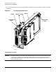
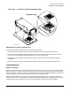
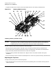
Figure 2-8 Processor Connector Alignment Tabs
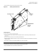
Replacing the Processor Extender Board
To replace the processor extender board, perform the following steps:
1. Ensure the extraction levers (see Figure 2-6) are positioned in the outward, unlocked position.
2. Align the processor extender board with the front and rear card guides. The end of the board which is
closer to the CPU module(s) should be toward the front of the server chassis.
3. Slide the processor extender board down until it begins to seat in the socket located on the system
baseboard.
4. Push the extraction levers inward to the locked position to fully seat the processor extender board.
Installing Memory
Memory Load Order
DIMMs are installed on memory extender boards located in the top service bay. If only one memory extender
board is installed, it must be located in slot 0. (See Figure 2-5.) A maximum of two memory extender boards
may be installed per system. Each memory extender board can hold up to 24 DIMMs. DIMMs of different size
can be installed on a memory extender board, but they must be grouped by size.
By replacing the DIMMs in your server, or installing additional DIMMS, you can increase the amount of
memory in your server. Several different DIMM sets are available. The DIMMs are listed in your hp Integrity
rx5670 Operation and Maintenance Guide, and at http://www.hp.com (search for keyword rx5670).
procsoctabs
Alignment Tabs