
Hardware Installation Guide - HP Integrity rx5670 (A6837B/A6838B)


Chapter 2
Installing Additional Components
Installing Processors and Memory
30
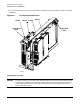
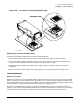
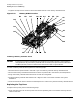
7. Tighten the captive T-15 screws to secure the DIMM retainer to the memory extender board.
Figure 2-10 Memory DIMM Location
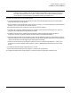
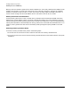
Installing a Memory Extender Board
CAUTION Ensure that a memory extender board is installed in slot MX0 (right slot). If the system is
configured with only one memory extender board a memory filler panel must be installed in
slot MX1 (left slot). Failure to observe this caution will result in system failure.
To install a memory extender board, perform the following steps:
1. Remove the filler panel located in slot MX1 if you are installing a second memory extender board.
2. Ensure the memory extender board extraction levers are positioned in the outward, unlocked position.
3. Align the memory extender board with the front and rear card guides.
4. Slide the memory extender board down until it begins to seat in the socket located on the system
baseboard.
5. Push the extraction levers inward to the locked position in order to fully seat the memory extender board.
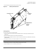
Replacing the Top Cover
To replace the top cover, perform the following steps:
1. Align the tabs at the rear of the top cover with the corresponding slots in the chassis and fully seat the
tabs into the slots.
membrd
A5
A3
A1
A4
A2
A0
B0
B2
B4 B1
B3 B5
D1
D3
D5
D0
D2
D4
C5 C3
C1
C4
C0
C2