
Hardware Installation Guide - HP Integrity rx5670 (A6837B/A6838B)


Chapter 3
Troubleshooting
hp Integrity rx5670 LED Indicators
47
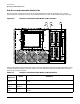
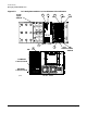
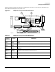
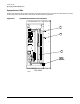
Figure 3-5 shows the location of indicators on the MP/SCSI Core I/O PCI card. Table 3-5 describes the I/O
status LEDs of the MP/SCSI Core I/O PCI card.
Figure 3-5 MP/SCSI Core I/O Card LED Indicators
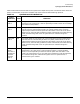
Table 3-5 MP/SCSI Core I/O Card LED Definitions
Figure
Reference
Name Definition
Figure 3-5,
item 1
ROM error
(DS2)
Lit (green) when an error has been detected in the management processor
ROM.
Figure 3-5,
item 2
Heartbeat
(DS3)
Lit (amber) when the management processor is operating.
Figure 3-5,
item 3
SLFTST /
failure
Lit (green) when a self test is executing. Flashes when an error has been
detected.
Figure 3-5,
item 4
10 link /
activity
Lit (green) when 10 Base T interface is active.
Figure 3-5,
item 5
Power ON Lit (green) when 10 Base T interface is active.
Figure 3-5,
item 6
100 link /
activity
Lit (green) when 100 Base T interface is active.
mpioleds
TOC
Switch
MP
Reset
Switch
5 6
4
3
1
2