
Hardware Installation Guide - HP Integrity rx5670 (A6837B/A6838B)


Chapter 3
Troubleshooting
hp Integrity rx5670 LED Indicators
53
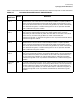
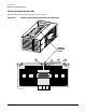
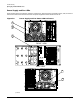
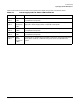
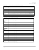
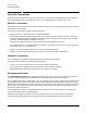
Table 3-8 describes the status LEDs on the memory extender board. Open the top cover to view these LEDs.
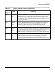
Table 3-8 Memory Extender Board LED Definitions
Figure
Reference
Name Definition
Figure 3-8,
item 1
1.5V and
2.5V power
ok
(DS1)
Lit (green) when the 1.5V and 2.5V power rails in the memory extender board
are within specifications. (The DC source is monitored by firmware. If a power
problem exists, it will be reported by firmware and server power will shut
down.) If this LED is out (while others are lit), the most likely problems (in
order of likelihood) are: malfunctioning LED, malfunctioning LED circuit on
memory extender board.
Figure 3-8,
item 2
Power
module 1
OK
(DS2)
Lit (green) when power module 1 is operating within specifications. (Memory
errors will be detected and reported in error messages.) If this LED is out
(while others are lit) and no errors have been reported, the most likely
problems (in order of likelihood) are: the associated power module,
malfunctioning LED, malfunctioning LED circuit on memory extender board.
Figure 3-8,
item 3
Power
module 2
OK
(DS3)
Lit (green) when the power module 2 is operating within specifications.
(Memory errors will be detected and reported in error messages.) If this LED
is out (while others are lit) and no errors have been reported, the most likely
problems (in order of likelihood) are: the associated power module,
malfunctioning LED, malfunctioning LED circuit on memory extender board.
Figure 3-8,
item 4
Power
module 3
OK
(DS4)
Lit (green) when power module 3 is operating within specifications. (Memory
errors will be detected and reported in error messages.) If this LED is out
(while others are lit) and no errors have been reported, the most likely
problems (in order of likelihood) are: the associated power module,
malfunctioning LED, malfunctioning LED circuit on memory extender board.