hp Integrity rx5670 Site Preparation Guide Product ID: A6837B/A6838B Manufacturing Part Number : rx5670_SitePrep July 2003 U.S.A. © Copyright 2003, Hewlett-Packard Development Company, L.P.
Legal Notices The information in this document is subject to change without notice. Hewlett-Packard makes no warranty of any kind with regard to this manual, including, but not limited to, the implied warranties of merchantability and fitness for a particular purpose. Hewlett-Packard shall not be held liable for errors contained herein or direct, indirect, special, incidental or consequential damages in connection with the furnishing, performance, or use of this material. Restricted Rights Legend.
Contents 1. System Specifications System Configuration . . . . . . . . . . . . . . . . . . . . . . . . . . . . . . . . . . . . . . . . . . . . . . . . . . . . . . . . . . . . . . . . . Dimensions and Weights . . . . . . . . . . . . . . . . . . . . . . . . . . . . . . . . . . . . . . . . . . . . . . . . . . . . . . . . . . . . . . . Component Dimensions . . . . . . . . . . . . . . . . . . . . . . . . . . . . . . . . . . . . . . . . . . . . . . . . . . . . . . . . . . . . . . System Weight . . . . . . . . . .
Contents Power Cable . . . . . . . . . . . . . . . . . . . . . . . . . . . . . . . . . . . . . . . . . . . . . . . . . . . . . . . . . . . . . . . . . . . . . . . . 43 Glossary . . . . . . . . . . . . . . . . . . . . . . . . . . . . . . . . . . . . . . . . . . . . . . . . . . . . . . . . . . . . . . . . . . . .
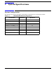
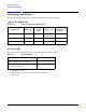
1 System Specifications System Configuration The following table lists the minimum and maximum configurations for an hp Integrity rx5670.
System Specifications Dimensions and Weights Dimensions and Weights This section provides dimensions and weights of hp Integrity rx5670 components. Component Dimensions Table 1-2 Server Component Dimensions Component Depth/ Length (cm) Width (cm) Height (cm) Maximum Quantity per Cabinet Cabinet 17.60 (44.70) 30.00 (76.2) 12.00 [7 EIA Units] (30.48) N/A Power Supplies 3.9 (9.91) 16.5 (41.91) 3.9 (9.91) 3 PCI Cards a varies varies varies 12 a.
System Specifications Electrical Specifications Electrical Specifications This section provides electrical specifications for the system. Circuit Breaker The Marked Electrical for the HP Server is 13 amps. The recommended circuit breaker size is 15 amps for North America. For countries outside North America, consult the local electrical authority that has jurisdiction for the recommended circuit breaker size. The system contains three power receptacles located at the bottom rear bulkhead.
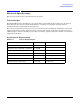
System Specifications Electrical Specifications Component Power Requirements Typical Power Consumptiona Table 1-5 CPU’s DIMM’s (Sets of 4) PCI Cards Volt Amps Watts (AC) Amps @ 115V with 3 Power Supplies Amps @ 230V with 3 Power Supplies 1 1 2 510 500 4.43 2.22 1 4 6 595 583 5.17 2.58 1 8 10 690 676 6.00 3.00 2 1 2 575 563 5.00 2.50 2 4 6 673 660 5.85 2.93 2 8 10 784 768 6.82 3.41 4 1 2 707 693 6.15 3.07 4 4 6 803 787 6.98 3.
System Specifications Environmental Specifications Environmental Specifications This section provides the temperature/humidity requirements, noise emission, and air flow specifications for the HP Server. Temperature and Humidity Specifications Ambient intake air temperature is often different from ambient room temperature; you should measure the operating temperature and humidity directly in front of the cabinet cooling air intakes rather than just checking ambient room conditions.
System Specifications Environmental Specifications 10 Chapter 1
2 General Site Preparation Guidelines The following information provides general principles and practices to consider before the installation or operation of an hp Integrity rx5670. Electrical Factors NOTE Electrical practices and suggestions in this guide are based on North American practices. For regions and areas outside North America, local electrical codes will take precedence over North American electrical codes.
General Site Preparation Guidelines Electrical Factors • Smoke detectors • Fire and temperature alarms • Fire extinguishing system Additional safety devices are: • Circuit breakers • An emergency power cutoff switch • Devices specific to the geographic location i.e., earthquake protection Lighting Requirements for Equipment Servicing Adequate lighting and utility outlets in a computer room reduce the possibility of accidents during equipment servicing.
General Site Preparation Guidelines Electrical Factors Sources of Voltage Fluctuations Voltage fluctuations, sometimes called glitches, affect the quality of electrical power.
General Site Preparation Guidelines Electrical Factors Power System Protection The hp Integrity rx5670 can be protected from the sources of many of these electrical disturbances by using: • A dedicated power distribution system • Power conditioning equipment • Over- and under-voltage detection and protection circuits • Screening to cancel out the effects of undesirable transmissions • Lightning arresters on power cables to protect equipment against electrical storms Precautions have been taken dur
General Site Preparation Guidelines Electrical Factors Grounding Systems IT Power System This product has not been evaluated for connection to an IT power system (an AC distribution system having no direct connection to earth according to IEC 60950).
General Site Preparation Guidelines Electrical Factors NOTE In some cases power distribution system green (green/yellow) wire ground conductors are too long and inductive to provide adequate high frequency ground return paths. Therefore, a ground strap (customer-supplied) should be used for connecting the system cabinet to the site grounding grid (customer-supplied). When connecting this ground, ensure that the raised floor is properly grounded for high frequency.
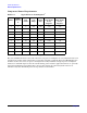
General Site Preparation Guidelines Electrical Factors Raised Floor “High Frequency Noise” Grounding If a raised floor system is used, install a complete signal grounding grid for maintaining equal potential over a broad band of frequencies. The grounding grid should be connected to the equipment cabinet and electrical service entrance ground at multiple connection points using a minimum #6 AWG (16 mm2) wire ground conductor. The following figure illustrates a metallic strip grounding system.
General Site Preparation Guidelines Electrical Factors Figure 2-1 Raised Floor Metal Strip Ground System 60SP010A 11/30/99 18 Chapter 2
General Site Preparation Guidelines Electrical Factors Equipment Grounding Implementation Details Connect all HP equipment cabinets to the site ground grid as follows: Step 1. Attach one end of each ground strap to the applicable cabinet ground lug. Step 2. Attach the other end to the nearest pedestal base (raised floor) or cable trough ground point (nonraised floor). Step 3. Check that the braid contact on each end of the ground strap consists of a terminal and connection hardware (a 1/4-in. [6.
General Site Preparation Guidelines Environmental Elements Environmental Elements The following environmental elements can affect an hp Integrity rx5670 installation: • Computer room preparation • Cooling requirements • Humidity level • Air conditioning ducts • Dust and pollution control • Electrostatic discharge (ESD) prevention • Acoustics (noise reduction) Computer Room Preparation The following guidelines are recommended when preparing a computer room for an hp Integrity rx5670: • Locate
General Site Preparation Guidelines Environmental Elements • Air distribution • System controls adequate to maintain the computer room within specified operating ranges Lighting and personnel must also be included. For example, a person dissipates about 450 BTUs per hour while performing a typical computer room task. At altitudes above 10,000 feet (3048 m), the lower air density reduces the cooling capability of air conditioning systems.
General Site Preparation Guidelines Environmental Elements • Underfloor air distribution system—Downflow air conditioning equipment located on the raised floor of the computer room uses the cavity beneath the raised floor as a plenum for the supply air. Return air from an underfloor air distribution system can be ducted return air (DRA) above the ceiling. Perforated floor panels (available from the raised floor manufacturer) should be located around the front of the system cabinets.
General Site Preparation Guidelines Environmental Elements Dust and Pollution Control Computer equipment can be adversely affected by dust and microscopic particles in the site environment. Specifically, disk drives, tape drives, and some other mechanical devices can have bearing failures resulting from airborne abrasive particles. Dust may also blanket electronic components like printed circuit boards, causing premature failure due to excess heat and/or humidity build up on the boards.
General Site Preparation Guidelines Environmental Elements Although this problem is relatively rare, it may be an issue within your computer room. Since metallic contamination can cause permanent or intermittent failures on your electronic equipment, Hewlett-Packard strongly recommends that your site be evaluated for metallic particulate contamination before installation of electronic equipment. ESD Prevention Static charges (voltage levels) occur when objects are separated or rubbed together.
General Site Preparation Guidelines Environmental Elements • Dropped ceiling—Cover with a commercial grade of fire-resistant, acoustic rated, fiberglass ceiling tile. • Sound deadening—Cover the walls with curtains or other sound deadening material. • Removable partitions—Use foam rubber models for most effectiveness.
General Site Preparation Guidelines Facility Characteristics Facility Characteristics This section contains information about facility characteristics that must be considered for the installation or operation of an hp Integrity rx5670.
General Site Preparation Guidelines Facility Characteristics Floor Loading Terms Table 2-2 Floor Loading Term Definitions Term Definition Dead load The weight of the raised panel floor system, including the understructure. Expressed in lb/ft2 (kg/m2). Live load The load that the floor system can safely support. Expressed in lb/ft2 (kg/m2). Concentrated load The load that a floor panel can support on a 1-in2 (6.
General Site Preparation Guidelines Facility Characteristics Table 2-3 Typical Raised Floor Specifications (Continued) Itema Rating Concentrated loadb 1250 lb (567 kg) Ultimate load 4,000 lb (1814 kg) per panel Rolling load 400 lb (181 kg) Average floor load 500 lb (227 kg) a. From Table 2-2 on page 27 b. With 0.08 in (0.2 cm) of span maximum deflection Windows Avoid housing computers in a room with windows. Sunlight entering a computer room may cause problems.
General Site Preparation Guidelines Space Requirements Space Requirements This section contains information about space requirements for an hp Integrity rx5670. This data should be used as the basic guideline for space plan developments. Other factors, such as airflow, lighting, and equipment space requirements must also be considered. Delivery Space Requirements There should be enough clearance to move equipment safely from the receiving area to the computer room.
General Site Preparation Guidelines Space Requirements • 30 Equipment cable routing Chapter 2
General Site Preparation Guidelines Conversion Factors and Formulas Conversion Factors and Formulas The conversion factors provided in this section are intended to ease data calculation for systems that do not conform specifically to the configurations listed in this Site Preparation Guide. Listed below are the conversion factors used in this document, as well as additional conversion factors which may be helpful in determining those factors required for site planning.
General Site Preparation Guidelines Sample of an Installation Schedule Sample of an Installation Schedule The following schedule lists the sequence of events for a typical system installation: • 60 days before installation — Floor plan design completed and mailed to Hewlett-Packard (if required to be an HP task) • 30 days before installation — Primary power and air conditioning installation completed — Telephone and data cables installed — Fire protection equipment installed — Major facility changes com
General Site Preparation Guidelines Sample Site Inspection Checklist Sample Site Inspection Checklist Table 2-4 Customer and Hewlett-Packard Information Customer Information Name: Phone No: Street Address: City: or Town: State or Province: Country: Zip or postal code: Primary customer contact: Phone No.: Secondary customer contact: Phone No.: Traffic coordinator: Phone No.
General Site Preparation Guidelines Sample Site Inspection Checklist Table 2-5 Site Inspection Checklist (Continued) Please check either Yes or No. If No, include comment# or date 7. Are there channels or cutouts for cable routing? 8. Is there a remote console telephone line available with an RJ11 jack? 9. Is a telephone line available? 10. Are customer supplied peripheral cables and LAN cables available and of the proper type? 11. Are floor tiles in good condition and properly braced? 12.
General Site Preparation Guidelines Sample Site Inspection Checklist Table 2-5 Site Inspection Checklist (Continued) Please check either Yes or No. If No, include comment# or date 23. Is there a telephone available for emergency purposes? 24. Is there a fire protection system in the computer room? 25. Is antistatic flooring installed? 26. Are there any equipment servicing hazards (loose ground wires, poor lighting, etc.)? Comment or Date Cooling No. Area or condition 27.
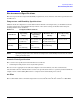
General Site Preparation Guidelines Delivery Survey Delivery Survey The delivery survey forms list delivery or installation requirements. If any of the items on the list apply, enter the appropriate information in the areas provided on the form. Special instructions or recommendations should be entered on the special instructions or recommendations form.
General Site Preparation Guidelines Delivery Survey Figure 2-2 Delivery Survey (Part 1) 60SP018A 12/7/99 Chapter 2 37
General Site Preparation Guidelines Delivery Survey Figure 2-3 Delivery Survey (Part 2) 60SP019A 11/24/99 38 Chapter 2
3 Power Plug Configuration There are several different power cables designed for use with HP Servers. The region the server ships to will determine which power cable ships with the server. The following provides the site preparation specialist with the knowledge of what to expect to receive based on the regional shipping destination. Female End of Power Cable The female end of the power cable is a C15 type plug that mates with the receptacle in each power supply installed in the HP Server.
Power Plug Configuration Male End of Power Cable Male End of Power Cable The male plug on the other end of the power cable will vary depending on the region the HP Server is shipped to. Several examples follow though this list is not meant to be all inclusive.
Power Plug Configuration Male End of Power Cable Figure 3-7 L6-30 Plug fig007 Figure 3-8 NEMA 5-20P Plug Figure 3-9 ISI 32 Plug Chapter 3 41
Power Plug Configuration Male End of Power Cable Figure 3-10 42 GB 1002 Plug Chapter 3
Power Plug Configuration Power Cable Power Cable The power cable length and configuration will vary based on the region the server ships to. This is an example of one power cable configuration used to supply power to the server.
Power Plug Configuration Power Cable 44 Chapter 3
Glossary A-B Apparent power A value of power for AC circuits that is calculated as the product of RMS current times RMS voltage, without taking the power factor into account. ASHRAE Standard 52-76 Industry standard for air filtration efficiency set forth by the American Society of Heating, Refrigerating, and Air-Conditioning Engineers, Inc. ASL Above sea level. board A printed circuit assembly (PCA). Also called a card or adapter. Btu/h The abbreviation for British thermal units.
Glossary PCA operational continuity. The documents cover both physical requirements including: Space Planning, Temperature, Humidity, Fire, Earthquake, Vibration, Transportation, Acoustical, Air Quality and Illumination; and electrical criteria including: Electrostatic Discharge (ESD), Electromagnetic Interference (EMI), Lightning and AC Power Fault, Steady State Power Induction, Corrosion, DC Potential Difference, Electrical Safety and Bonding and Grounding.