
HP Integrity iLO 2 Operations Guide
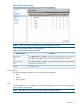
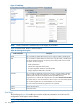
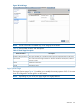
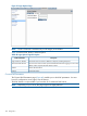
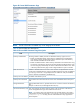
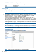
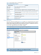
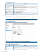
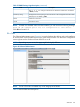
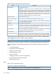
Table Of Contents
- HP Integrity iLO 2 Operations Guide
- Contents
- About This Document
- 1 Introduction to iLO 2
- Features
- Standard Features
- Always-On Capability
- Virtual Front Panel
- Multiple Access Methods
- Security
- User Access Control
- Multiple Users
- IPMI over LAN
- System Management Homepage
- Firmware Upgrades
- Internal Subsystem Information
- DHCP and DNS Support
- Group Actions
- Group Actions Using HP SIM
- SNMP
- SMASH
- SM CLP
- Mirrored Console
- Remote Power Control
- Power Regulation
- Event Logging
- Advanced Features
- Standard Features
- Obtaining and Activating iLO 2 Advanced Pack Licensing
- Supported Systems and Required Components and Cables
- Integrity iLO 2 Supported Browsers and Client Operating Systems
- Security
- Features
- 2 Ports and LEDs
- 3 Getting Connected to iLO 2
- 4 Logging In to iLO 2
- 5 Adding Advanced Features
- Lights-Out Advanced KVM Card for sx2000 Servers
- Lights-Out Advanced KVM card Requirements
- Configuring the Lights-Out Advanced KVM Card
- Lights-Out Advanced KVM Card IRC Feature
- Lights-Out Advanced KVM Card vMedia Feature
- Installing the Lights-Out Advanced KVM Card in a Server
- Lights-Out Advanced KVM Card Quick Setup Steps
- Using Lights-Out Advanced KVM Features
- Mid Range PCI Backplane Power Behavior
- Troubleshooting the Lights-Out Advanced KVM Card
- Core I/O Card Configurations
- Supported PCI-X Slots
- Upgrading the Lights-Out Advanced KVM Card Firmware
- Lights-Out Advanced KVM Card for sx2000 Servers
- 6 Accessing the Host (Operating System) Console
- 7 Configuring DHCP, DNS, LDAP, and Schema-Free LDAP
- 8 Using iLO 2
- Text User Interface
- MP Command Interfaces
- MP Main Menu
- MP Main Menu Commands
- CO (Console): Leave the MP Main Menu and enter console mode
- VFP (Virtual Front Panel): Simulate the display panel
- CM (Command Mode): Enter command mode
- SMCLP (Server Management Command Line Protocol): Switch to the SMASH SMCLP
- CL (Console Log): View the history of the console output
- SL (Show Logs): View events in the log history
- HE (Help): Display help for the menu or command in the MP Main Menu
- X (Exit): Exit iLO 2
- MP Main Menu Commands
- Command Menu
- Command Line Interface Scripting
- Command Menu Commands and Standard Command Line Scripting Syntax
- BP: Reset BMC passwords
- BLADE: Display BLADE parameters
- CA: Configure asynchronous local serial port
- DATE: Display date
- DC (Default Configuration): Reset all parameters to default configurations
- DF: Display FRU information
- DI: Disconnect LAN, WEB, SSH, or Console
- DNS: DNS settings
- FW: Upgrade the MP firmware
- HE: Display help for menu or command in command menu interface
- ID: System information settings
- IT: Inactivity timeout settings
- LC: LAN configuration usage
- LDAP: LDAP directory settings
- LM: License management
- LOC: Locator UID LED configuration
- LS: LAN status
- PC: Power control access
- PM: Power regulator mode
- PR: Power restore policy configuration
- PS: Power status
- RB: Reset BMC
- RS: Reset system through the RST signal
- SA: Set access LAN/WEB/SSH/IPMI over LAN ports
- SNMP: Configure SNMP parameters
- SO: Security option help
- SS: System Status
- SYSREV: Firmware revisions
- TC: System reset through INIT or TOC signal
- TE: Send a message to other mirroring terminals
- UC: User Configuration (users, passwords, and so on)
- WHO: Display a list of iLO 2 connected users
- XD: iLO 2 Diagnostics or reset
- Web GUI
- System Status
- Remote Serial Console
- Integrated Remote Console
- Virtual Media
- Power Management
- Administration
- BL c-Class
- Help
- SMASH Server Management Command Line Protocol
- SM CLP Features and Functionality Overview
- Accessing the SM CLP Interface
- Using the SM CLP Interface
- SM CLP Syntax
- System1 Target
- System Reset Power Status and Power Control
- Map1 (iLO 2) Target
- Text Console Services
- Firmware Revision Display and Upgrade
- Remote Access Configuration
- Network Configuration
- User Accounts Configuration
- LDAP Configuration
- Text User Interface
- 9 Installing and Configuring Directory Services
- Directory Services
- Directory Services for Active Directory
- Directory Services for eDirectory
- Installing and Initializing Snap-In for eDirectory
- Example: Creating and Configuring Directory Objects for Use with iLO 2 Devices in eDirectory
- Directory Services Objects for eDirectory
- Setting Role Restrictions
- Setting Time Restrictions
- Setting Lights-Out Management Device Rights
- Installing Snap-Ins and Extending Schema for eDirectory on a Linux Platform
- Using the LDAP Command to Configure Directory Settings in iLO 2
- User Login Using Directory Services
- Certificate Services
- Directory-Enabled Remote Management
- Directory Services Schema (LDAP)
- Glossary
- Index

Table 53 Onboard Administrator Page Description
DescriptionField
The IP address of the OA.
IMPORTANT: Integrity iLO 2 must have a reachable IP address as the default gateway
address. Since the OA is always reachable, HP recommends using the OA IP address
as the gateway address for Integrity iLO 2. If you use the Enclosure IP mode, this solution
works during a failover. In the Enclosure IP mode, a static IP address is assigned to the
active OA, and during a failover, the same IP address follows the active OA. If the OA
IP address is assigned using DHCP, the solution does not work. In such instances, HP
recommends manually changing the iLO 2 gateway address.
OA IP Address
The MAC address of the OA.OA MAC Address
Click this button to launch the Onboard Administrator Sign In page.Active OA Sign In Page
This is used to logically group together enclosures in a rack. The rack name is shared
with the other enclosures in the rack.
Rack Name
This is the rack unique identifier.Rack UID
The enclosure can support as many as eight HP Integrity server blades. When viewed
from the rack front, the bays are numbered from left to right and from 1 to 8. The bay
number is used to locate and identify a server blade.
Bay Number
This is used to logically group together the server blades installed in the same enclosure.
The enclosure name is shared with the other servers in the enclosure.
Enclosure Name
This displays the health of the enclosure.Enclosure Health
This allows you to turn the enclosure Locator UID LED on or off. The iLO Configuration
access right is needed. If a user does not have sufficient rights, the button is disabled.
Enclosure Locator UID LED
Before setting up the HP BladeSystem OA, HP recommends that you read the HP BladeSystem
Onboard Administrator User Guide on the HP website at:
http://h20000.www2.hp.com/bc/docs/support/SupportManual/c00705292/c00705292.pdf
Reading this guide ensures that you will obtain an overall understanding of the HP BladeSystem
OA and that you properly complete the initial setup to facilitate proper functioning of the OA.
The HP BladeSystem Onboard Administrator User Guide provides the following information in
detail:
• Access Requirements
• Running the OA for the first time
• Signing in to the OA GUI
• Running the setup wizard
• Using online help
• Changing enclosure and device configurations
• Recovering the administrator password
• Flash disaster recovery
Help
The iLO 2 has a robust help system.
To access iLO 2 help, click the Help tab.
NOTE: Depending on your server, this page might look slightly different.
140 Using iLO 2