
HP Integrity iLO 2 Operations Guide
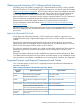
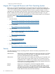
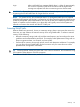

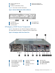
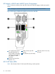
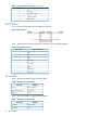
Table Of Contents
- HP Integrity iLO 2 Operations Guide
- Contents
- About This Document
- 1 Introduction to iLO 2
- Features
- Standard Features
- Always-On Capability
- Virtual Front Panel
- Multiple Access Methods
- Security
- User Access Control
- Multiple Users
- IPMI over LAN
- System Management Homepage
- Firmware Upgrades
- Internal Subsystem Information
- DHCP and DNS Support
- Group Actions
- Group Actions Using HP SIM
- SNMP
- SMASH
- SM CLP
- Mirrored Console
- Remote Power Control
- Power Regulation
- Event Logging
- Advanced Features
- Standard Features
- Obtaining and Activating iLO 2 Advanced Pack Licensing
- Supported Systems and Required Components and Cables
- Integrity iLO 2 Supported Browsers and Client Operating Systems
- Security
- Features
- 2 Ports and LEDs
- 3 Getting Connected to iLO 2
- 4 Logging In to iLO 2
- 5 Adding Advanced Features
- Lights-Out Advanced KVM Card for sx2000 Servers
- Lights-Out Advanced KVM card Requirements
- Configuring the Lights-Out Advanced KVM Card
- Lights-Out Advanced KVM Card IRC Feature
- Lights-Out Advanced KVM Card vMedia Feature
- Installing the Lights-Out Advanced KVM Card in a Server
- Lights-Out Advanced KVM Card Quick Setup Steps
- Using Lights-Out Advanced KVM Features
- Mid Range PCI Backplane Power Behavior
- Troubleshooting the Lights-Out Advanced KVM Card
- Core I/O Card Configurations
- Supported PCI-X Slots
- Upgrading the Lights-Out Advanced KVM Card Firmware
- Lights-Out Advanced KVM Card for sx2000 Servers
- 6 Accessing the Host (Operating System) Console
- 7 Configuring DHCP, DNS, LDAP, and Schema-Free LDAP
- 8 Using iLO 2
- Text User Interface
- MP Command Interfaces
- MP Main Menu
- MP Main Menu Commands
- CO (Console): Leave the MP Main Menu and enter console mode
- VFP (Virtual Front Panel): Simulate the display panel
- CM (Command Mode): Enter command mode
- SMCLP (Server Management Command Line Protocol): Switch to the SMASH SMCLP
- CL (Console Log): View the history of the console output
- SL (Show Logs): View events in the log history
- HE (Help): Display help for the menu or command in the MP Main Menu
- X (Exit): Exit iLO 2
- MP Main Menu Commands
- Command Menu
- Command Line Interface Scripting
- Command Menu Commands and Standard Command Line Scripting Syntax
- BP: Reset BMC passwords
- BLADE: Display BLADE parameters
- CA: Configure asynchronous local serial port
- DATE: Display date
- DC (Default Configuration): Reset all parameters to default configurations
- DF: Display FRU information
- DI: Disconnect LAN, WEB, SSH, or Console
- DNS: DNS settings
- FW: Upgrade the MP firmware
- HE: Display help for menu or command in command menu interface
- ID: System information settings
- IT: Inactivity timeout settings
- LC: LAN configuration usage
- LDAP: LDAP directory settings
- LM: License management
- LOC: Locator UID LED configuration
- LS: LAN status
- PC: Power control access
- PM: Power regulator mode
- PR: Power restore policy configuration
- PS: Power status
- RB: Reset BMC
- RS: Reset system through the RST signal
- SA: Set access LAN/WEB/SSH/IPMI over LAN ports
- SNMP: Configure SNMP parameters
- SO: Security option help
- SS: System Status
- SYSREV: Firmware revisions
- TC: System reset through INIT or TOC signal
- TE: Send a message to other mirroring terminals
- UC: User Configuration (users, passwords, and so on)
- WHO: Display a list of iLO 2 connected users
- XD: iLO 2 Diagnostics or reset
- Web GUI
- System Status
- Remote Serial Console
- Integrated Remote Console
- Virtual Media
- Power Management
- Administration
- BL c-Class
- Help
- SMASH Server Management Command Line Protocol
- SM CLP Features and Functionality Overview
- Accessing the SM CLP Interface
- Using the SM CLP Interface
- SM CLP Syntax
- System1 Target
- System Reset Power Status and Power Control
- Map1 (iLO 2) Target
- Text Console Services
- Firmware Revision Display and Upgrade
- Remote Access Configuration
- Network Configuration
- User Accounts Configuration
- LDAP Configuration
- Text User Interface
- 9 Installing and Configuring Directory Services
- Directory Services
- Directory Services for Active Directory
- Directory Services for eDirectory
- Installing and Initializing Snap-In for eDirectory
- Example: Creating and Configuring Directory Objects for Use with iLO 2 Devices in eDirectory
- Directory Services Objects for eDirectory
- Setting Role Restrictions
- Setting Time Restrictions
- Setting Lights-Out Management Device Rights
- Installing Snap-Ins and Extending Schema for eDirectory on a Linux Platform
- Using the LDAP Command to Configure Directory Settings in iLO 2
- User Login Using Directory Services
- Certificate Services
- Directory-Enabled Remote Management
- Directory Services Schema (LDAP)
- Glossary
- Index
4
Enclosure Link-Up Port
1
OA/iLO Network Port
2
OA Bay 1
5
Enclosure Link-Down Port
3
OA Bay 2 (redundant if used)
Figure 2 shows the OA LEDs and buttons.
Figure 2 Onboard Administrator LEDs and Buttons
4
OA Health LED
1
OA UID LED
2
Enclosure UID LED
5
OA Reset Button
3
OA Active LED
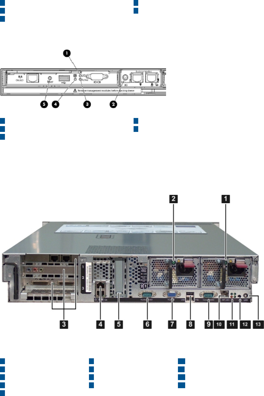
HP Integrity rx2660 Server Components
Figure 3 shows the rear view of the HP Integrity rx2660 server.
The system LAN functionality is integrated into the system board.
Figure 3 HP Integrity rx2660 Server Rear View
10
MP LAN Port
6
Auxiliary Serial Port
1
Power Supply 1 and LED
2
Power Supply 2 and LED
11
iLO 2 MP Status LEDs
7
VGA Port
8
USB Ports
3
PCI-x/PCIe Slots
12
iLO 2 MP Reset Button
1394
Core LAN Ports UID Button/LEDConsole Serial Port
(RS-232)
5
Smart Array P400
Controller Slot
HP Integrity rx2660 Server Components 27