
HP Integrity iLO 2 Operations Guide
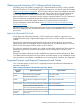

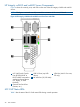
Table Of Contents
- HP Integrity iLO 2 Operations Guide
- Contents
- About This Document
- 1 Introduction to iLO 2
- Features
- Standard Features
- Always-On Capability
- Virtual Front Panel
- Multiple Access Methods
- Security
- User Access Control
- Multiple Users
- IPMI over LAN
- System Management Homepage
- Firmware Upgrades
- Internal Subsystem Information
- DHCP and DNS Support
- Group Actions
- Group Actions Using HP SIM
- SNMP
- SMASH
- SM CLP
- Mirrored Console
- Remote Power Control
- Power Regulation
- Event Logging
- Advanced Features
- Standard Features
- Obtaining and Activating iLO 2 Advanced Pack Licensing
- Supported Systems and Required Components and Cables
- Integrity iLO 2 Supported Browsers and Client Operating Systems
- Security
- Features
- 2 Ports and LEDs
- 3 Getting Connected to iLO 2
- 4 Logging In to iLO 2
- 5 Adding Advanced Features
- Lights-Out Advanced KVM Card for sx2000 Servers
- Lights-Out Advanced KVM card Requirements
- Configuring the Lights-Out Advanced KVM Card
- Lights-Out Advanced KVM Card IRC Feature
- Lights-Out Advanced KVM Card vMedia Feature
- Installing the Lights-Out Advanced KVM Card in a Server
- Lights-Out Advanced KVM Card Quick Setup Steps
- Using Lights-Out Advanced KVM Features
- Mid Range PCI Backplane Power Behavior
- Troubleshooting the Lights-Out Advanced KVM Card
- Core I/O Card Configurations
- Supported PCI-X Slots
- Upgrading the Lights-Out Advanced KVM Card Firmware
- Lights-Out Advanced KVM Card for sx2000 Servers
- 6 Accessing the Host (Operating System) Console
- 7 Configuring DHCP, DNS, LDAP, and Schema-Free LDAP
- 8 Using iLO 2
- Text User Interface
- MP Command Interfaces
- MP Main Menu
- MP Main Menu Commands
- CO (Console): Leave the MP Main Menu and enter console mode
- VFP (Virtual Front Panel): Simulate the display panel
- CM (Command Mode): Enter command mode
- SMCLP (Server Management Command Line Protocol): Switch to the SMASH SMCLP
- CL (Console Log): View the history of the console output
- SL (Show Logs): View events in the log history
- HE (Help): Display help for the menu or command in the MP Main Menu
- X (Exit): Exit iLO 2
- MP Main Menu Commands
- Command Menu
- Command Line Interface Scripting
- Command Menu Commands and Standard Command Line Scripting Syntax
- BP: Reset BMC passwords
- BLADE: Display BLADE parameters
- CA: Configure asynchronous local serial port
- DATE: Display date
- DC (Default Configuration): Reset all parameters to default configurations
- DF: Display FRU information
- DI: Disconnect LAN, WEB, SSH, or Console
- DNS: DNS settings
- FW: Upgrade the MP firmware
- HE: Display help for menu or command in command menu interface
- ID: System information settings
- IT: Inactivity timeout settings
- LC: LAN configuration usage
- LDAP: LDAP directory settings
- LM: License management
- LOC: Locator UID LED configuration
- LS: LAN status
- PC: Power control access
- PM: Power regulator mode
- PR: Power restore policy configuration
- PS: Power status
- RB: Reset BMC
- RS: Reset system through the RST signal
- SA: Set access LAN/WEB/SSH/IPMI over LAN ports
- SNMP: Configure SNMP parameters
- SO: Security option help
- SS: System Status
- SYSREV: Firmware revisions
- TC: System reset through INIT or TOC signal
- TE: Send a message to other mirroring terminals
- UC: User Configuration (users, passwords, and so on)
- WHO: Display a list of iLO 2 connected users
- XD: iLO 2 Diagnostics or reset
- Web GUI
- System Status
- Remote Serial Console
- Integrated Remote Console
- Virtual Media
- Power Management
- Administration
- BL c-Class
- Help
- SMASH Server Management Command Line Protocol
- SM CLP Features and Functionality Overview
- Accessing the SM CLP Interface
- Using the SM CLP Interface
- SM CLP Syntax
- System1 Target
- System Reset Power Status and Power Control
- Map1 (iLO 2) Target
- Text Console Services
- Firmware Revision Display and Upgrade
- Remote Access Configuration
- Network Configuration
- User Accounts Configuration
- LDAP Configuration
- Text User Interface
- 9 Installing and Configuring Directory Services
- Directory Services
- Directory Services for Active Directory
- Directory Services for eDirectory
- Installing and Initializing Snap-In for eDirectory
- Example: Creating and Configuring Directory Objects for Use with iLO 2 Devices in eDirectory
- Directory Services Objects for eDirectory
- Setting Role Restrictions
- Setting Time Restrictions
- Setting Lights-Out Management Device Rights
- Installing Snap-Ins and Extending Schema for eDirectory on a Linux Platform
- Using the LDAP Command to Configure Directory Settings in iLO 2
- User Login Using Directory Services
- Certificate Services
- Directory-Enabled Remote Management
- Directory Services Schema (LDAP)
- Glossary
- Index
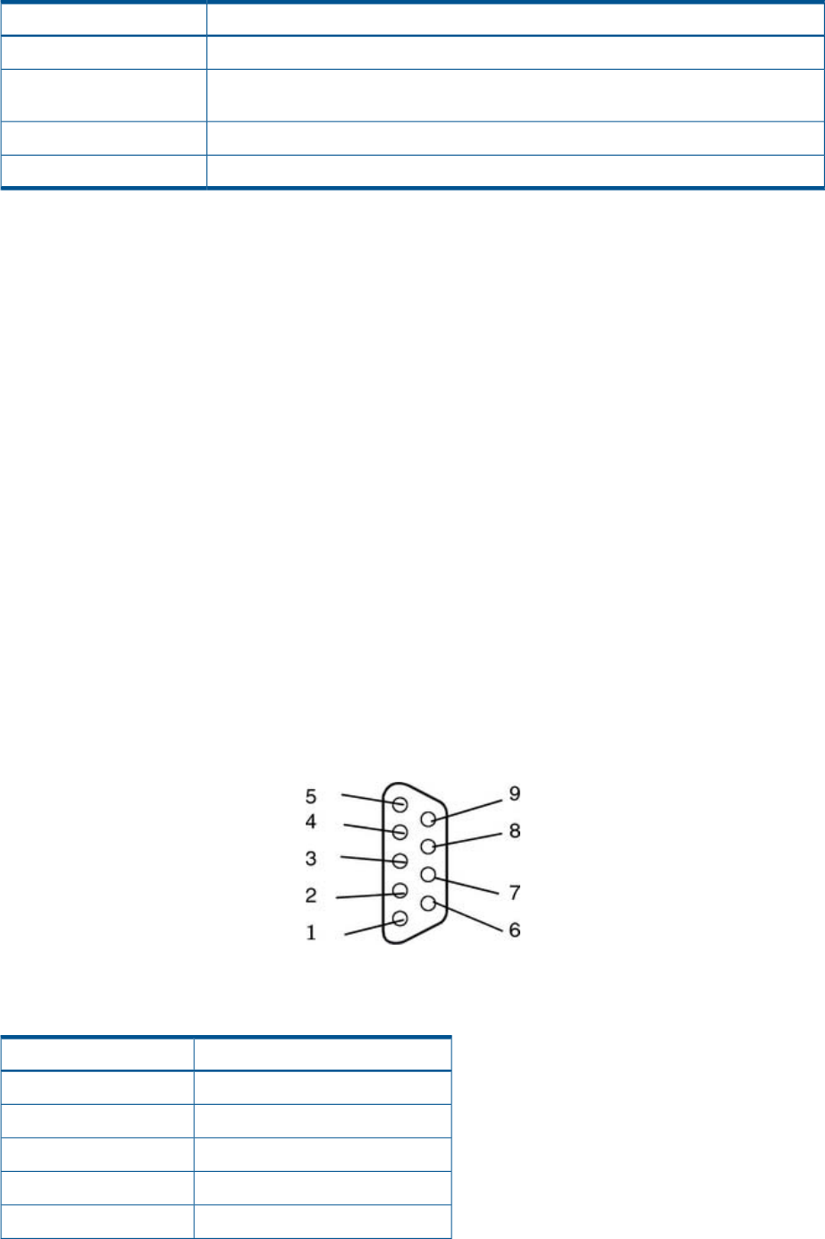
Table 3 iLO 2 MP Status LEDs
LED StateiLO 2 MP Status LED
Solid green.Standby Power
Off. The LED is solid amber when AC power is first applied. It remains solid amber for
a few seconds until the MP completes its self test; then the LED turns off.
iLO 2 MP Self Test
Flashing green.iLO 2 MP Heartbeat
Flashing green.BMC Heartbeat
iLO 2 MP Reset Button
The iLO 2 MP Reset button enables you to reset iLO 2 and reset the user-specific values to factory
default values. A momentary press causes a soft reset of iLO 2 when the button is released. A
greater than four second press causes a soft reset of iLO 2 upon release and resets local user
accounts and passwords to factory default values.
Resetting Local User Accounts and Passwords to Default Values
If iLO 2 user passwords are lost, or iLO 2 local user accounts are disabled and logging in through
LDAP directory server is unsuccessful because the directory server is down or directory settings
have not been configured properly in LDAP command, you can reset local user accounts and
passwords to their default values.
To reset local user accounts and passwords to default values:
1. Connect a serial terminal (or serial-cabled laptop with serial emulation) to the console serial
port.
2. Press and hold the iLO 2 MP Reset button for more than four seconds. iLO 2 reboots to factory
default settings automatically.
3. Respond to the prompt to reset local user accounts and passwords to default values.
Console Serial Port and Auxiliary Serial Port
Figure 5 shows the console serial port connector with numbered labels for each pin on each port.
Figure 5 Console Serial Port (RS-232) Connector
Table 4 maps the console serial port connector pin number to its signal description on each port.
Table 4 Console Serial Port Pinouts
Signal DescriptionPin Number
Not used1
Receives data2
Transmits data3
Not used4
Ground5
iLO 2 MP Reset Button 29