
HP Integrity iLO 2 Operations Guide
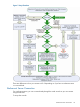
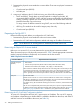
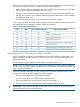
Table Of Contents
- HP Integrity iLO 2 Operations Guide
- Contents
- About This Document
- 1 Introduction to iLO 2
- Features
- Standard Features
- Always-On Capability
- Virtual Front Panel
- Multiple Access Methods
- Security
- User Access Control
- Multiple Users
- IPMI over LAN
- System Management Homepage
- Firmware Upgrades
- Internal Subsystem Information
- DHCP and DNS Support
- Group Actions
- Group Actions Using HP SIM
- SNMP
- SMASH
- SM CLP
- Mirrored Console
- Remote Power Control
- Power Regulation
- Event Logging
- Advanced Features
- Standard Features
- Obtaining and Activating iLO 2 Advanced Pack Licensing
- Supported Systems and Required Components and Cables
- Integrity iLO 2 Supported Browsers and Client Operating Systems
- Security
- Features
- 2 Ports and LEDs
- 3 Getting Connected to iLO 2
- 4 Logging In to iLO 2
- 5 Adding Advanced Features
- Lights-Out Advanced KVM Card for sx2000 Servers
- Lights-Out Advanced KVM card Requirements
- Configuring the Lights-Out Advanced KVM Card
- Lights-Out Advanced KVM Card IRC Feature
- Lights-Out Advanced KVM Card vMedia Feature
- Installing the Lights-Out Advanced KVM Card in a Server
- Lights-Out Advanced KVM Card Quick Setup Steps
- Using Lights-Out Advanced KVM Features
- Mid Range PCI Backplane Power Behavior
- Troubleshooting the Lights-Out Advanced KVM Card
- Core I/O Card Configurations
- Supported PCI-X Slots
- Upgrading the Lights-Out Advanced KVM Card Firmware
- Lights-Out Advanced KVM Card for sx2000 Servers
- 6 Accessing the Host (Operating System) Console
- 7 Configuring DHCP, DNS, LDAP, and Schema-Free LDAP
- 8 Using iLO 2
- Text User Interface
- MP Command Interfaces
- MP Main Menu
- MP Main Menu Commands
- CO (Console): Leave the MP Main Menu and enter console mode
- VFP (Virtual Front Panel): Simulate the display panel
- CM (Command Mode): Enter command mode
- SMCLP (Server Management Command Line Protocol): Switch to the SMASH SMCLP
- CL (Console Log): View the history of the console output
- SL (Show Logs): View events in the log history
- HE (Help): Display help for the menu or command in the MP Main Menu
- X (Exit): Exit iLO 2
- MP Main Menu Commands
- Command Menu
- Command Line Interface Scripting
- Command Menu Commands and Standard Command Line Scripting Syntax
- BP: Reset BMC passwords
- BLADE: Display BLADE parameters
- CA: Configure asynchronous local serial port
- DATE: Display date
- DC (Default Configuration): Reset all parameters to default configurations
- DF: Display FRU information
- DI: Disconnect LAN, WEB, SSH, or Console
- DNS: DNS settings
- FW: Upgrade the MP firmware
- HE: Display help for menu or command in command menu interface
- ID: System information settings
- IT: Inactivity timeout settings
- LC: LAN configuration usage
- LDAP: LDAP directory settings
- LM: License management
- LOC: Locator UID LED configuration
- LS: LAN status
- PC: Power control access
- PM: Power regulator mode
- PR: Power restore policy configuration
- PS: Power status
- RB: Reset BMC
- RS: Reset system through the RST signal
- SA: Set access LAN/WEB/SSH/IPMI over LAN ports
- SNMP: Configure SNMP parameters
- SO: Security option help
- SS: System Status
- SYSREV: Firmware revisions
- TC: System reset through INIT or TOC signal
- TE: Send a message to other mirroring terminals
- UC: User Configuration (users, passwords, and so on)
- WHO: Display a list of iLO 2 connected users
- XD: iLO 2 Diagnostics or reset
- Web GUI
- System Status
- Remote Serial Console
- Integrated Remote Console
- Virtual Media
- Power Management
- Administration
- BL c-Class
- Help
- SMASH Server Management Command Line Protocol
- SM CLP Features and Functionality Overview
- Accessing the SM CLP Interface
- Using the SM CLP Interface
- SM CLP Syntax
- System1 Target
- System Reset Power Status and Power Control
- Map1 (iLO 2) Target
- Text Console Services
- Firmware Revision Display and Upgrade
- Remote Access Configuration
- Network Configuration
- User Accounts Configuration
- LDAP Configuration
- Text User Interface
- 9 Installing and Configuring Directory Services
- Directory Services
- Directory Services for Active Directory
- Directory Services for eDirectory
- Installing and Initializing Snap-In for eDirectory
- Example: Creating and Configuring Directory Objects for Use with iLO 2 Devices in eDirectory
- Directory Services Objects for eDirectory
- Setting Role Restrictions
- Setting Time Restrictions
- Setting Lights-Out Management Device Rights
- Installing Snap-Ins and Extending Schema for eDirectory on a Linux Platform
- Using the LDAP Command to Configure Directory Settings in iLO 2
- User Login Using Directory Services
- Certificate Services
- Directory-Enabled Remote Management
- Directory Services Schema (LDAP)
- Glossary
- Index

1. Determine the physical access method to connect cables. There are two physical connections
to iLO 2 :
• Console serial port (RS-232)
• MP LAN port
2. Assign an IP address to the iLO 2 MP LAN using one of the following methods:
• DHCP and DDNS. Though there are several methods to configuring the LAN, HP
recommends DHCP with DNS. DHCP with DNS comes preconfigured with default factory
settings, including a default user account and password. Use the DNS name on the iLO
Network Information Tag on the server.
To assign a static IP address instead of using DHCP, use one of the following methods:
• ARP Ping. This method can be used for Integrity entry class only.
• Console serial port (RS-232)
Preparing to Set Up iLO 2
Perform the following tasks before you configure the iLO 2 MP LAN:
• Determine the physical access method to select and connect cables.
• Determine the iLO 2 MP LAN configuration method and assign an IP address if necessary.
NOTE: Server blade iLO 2s are assigned an IP address by the blade chassis OA.
Determining the Physical iLO 2 Access Method
Before you can access iLO 2, you must determine the correct physical connection method.
There are several ways you can physically connect to iLO 2. Table 9 lists the appropriate connection
method, required connection components, and connectors to the host console.
Table 9 Physical Connection Matrix
Required Connection ComponentsConnection Method
Console serial port
(RS-232)
• Host console
• Console serial port (RS-232) DB-9F to DB-9F cable (modem eliminator cable)
• Emulation terminal device (for example, a PC, laptop, or ASCII terminal)
These connection methods directly attach to the iLO 2 MP through the console serial port. This
is an RS-232 connection from a workstation to the server's iLO 2 MP console serial port. Serial
cable concentrators are used to provide switched access from one workstation to multiple
servers. Typically, the console serial port method is used by an administrator in the data center.
10/100 LAN cableLAN port
Remote access to the iLO 2 is a more convenient method. This remote access is through the
MP LAN port. Depending on your LAN administration, this can be restricted to the datacenter,
or extended outside the data center to your company's intranet.
For greater security, HP recommends restricting LAN access to well known, trusted and secured
networks.
The iLO 2 has a separate LAN port from the system LAN port. It requires a separate LAN drop,
IP address, and networking information from that of the operating system LAN port. See Figure 3
and Figure 4 (page 28) and use Table 9 to determine your physical connection method.
Determining the iLO 2 MP LAN Configuration Method
To access iLO 2 through the MP LAN, iLO 2 must acquire an IP address. The way iLO 2 acquires
an IP address is dependent upon whether DHCP is enabled or disabled on the server, and if DHCP
and DNS services are available to the server (see Table 10).
34 Getting Connected to iLO 2