
HP Integrity iLO 2 Operations Guide
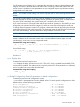
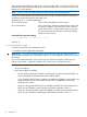
Table Of Contents
- HP Integrity iLO 2 Operations Guide
- Contents
- About This Document
- 1 Introduction to iLO 2
- Features
- Standard Features
- Always-On Capability
- Virtual Front Panel
- Multiple Access Methods
- Security
- User Access Control
- Multiple Users
- IPMI over LAN
- System Management Homepage
- Firmware Upgrades
- Internal Subsystem Information
- DHCP and DNS Support
- Group Actions
- Group Actions Using HP SIM
- SNMP
- SMASH
- SM CLP
- Mirrored Console
- Remote Power Control
- Power Regulation
- Event Logging
- Advanced Features
- Standard Features
- Obtaining and Activating iLO 2 Advanced Pack Licensing
- Supported Systems and Required Components and Cables
- Integrity iLO 2 Supported Browsers and Client Operating Systems
- Security
- Features
- 2 Ports and LEDs
- 3 Getting Connected to iLO 2
- 4 Logging In to iLO 2
- 5 Adding Advanced Features
- Lights-Out Advanced KVM Card for sx2000 Servers
- Lights-Out Advanced KVM card Requirements
- Configuring the Lights-Out Advanced KVM Card
- Lights-Out Advanced KVM Card IRC Feature
- Lights-Out Advanced KVM Card vMedia Feature
- Installing the Lights-Out Advanced KVM Card in a Server
- Lights-Out Advanced KVM Card Quick Setup Steps
- Using Lights-Out Advanced KVM Features
- Mid Range PCI Backplane Power Behavior
- Troubleshooting the Lights-Out Advanced KVM Card
- Core I/O Card Configurations
- Supported PCI-X Slots
- Upgrading the Lights-Out Advanced KVM Card Firmware
- Lights-Out Advanced KVM Card for sx2000 Servers
- 6 Accessing the Host (Operating System) Console
- 7 Configuring DHCP, DNS, LDAP, and Schema-Free LDAP
- 8 Using iLO 2
- Text User Interface
- MP Command Interfaces
- MP Main Menu
- MP Main Menu Commands
- CO (Console): Leave the MP Main Menu and enter console mode
- VFP (Virtual Front Panel): Simulate the display panel
- CM (Command Mode): Enter command mode
- SMCLP (Server Management Command Line Protocol): Switch to the SMASH SMCLP
- CL (Console Log): View the history of the console output
- SL (Show Logs): View events in the log history
- HE (Help): Display help for the menu or command in the MP Main Menu
- X (Exit): Exit iLO 2
- MP Main Menu Commands
- Command Menu
- Command Line Interface Scripting
- Command Menu Commands and Standard Command Line Scripting Syntax
- BP: Reset BMC passwords
- BLADE: Display BLADE parameters
- CA: Configure asynchronous local serial port
- DATE: Display date
- DC (Default Configuration): Reset all parameters to default configurations
- DF: Display FRU information
- DI: Disconnect LAN, WEB, SSH, or Console
- DNS: DNS settings
- FW: Upgrade the MP firmware
- HE: Display help for menu or command in command menu interface
- ID: System information settings
- IT: Inactivity timeout settings
- LC: LAN configuration usage
- LDAP: LDAP directory settings
- LM: License management
- LOC: Locator UID LED configuration
- LS: LAN status
- PC: Power control access
- PM: Power regulator mode
- PR: Power restore policy configuration
- PS: Power status
- RB: Reset BMC
- RS: Reset system through the RST signal
- SA: Set access LAN/WEB/SSH/IPMI over LAN ports
- SNMP: Configure SNMP parameters
- SO: Security option help
- SS: System Status
- SYSREV: Firmware revisions
- TC: System reset through INIT or TOC signal
- TE: Send a message to other mirroring terminals
- UC: User Configuration (users, passwords, and so on)
- WHO: Display a list of iLO 2 connected users
- XD: iLO 2 Diagnostics or reset
- Web GUI
- System Status
- Remote Serial Console
- Integrated Remote Console
- Virtual Media
- Power Management
- Administration
- BL c-Class
- Help
- SMASH Server Management Command Line Protocol
- SM CLP Features and Functionality Overview
- Accessing the SM CLP Interface
- Using the SM CLP Interface
- SM CLP Syntax
- System1 Target
- System Reset Power Status and Power Control
- Map1 (iLO 2) Target
- Text Console Services
- Firmware Revision Display and Upgrade
- Remote Access Configuration
- Network Configuration
- User Accounts Configuration
- LDAP Configuration
- Text User Interface
- 9 Installing and Configuring Directory Services
- Directory Services
- Directory Services for Active Directory
- Directory Services for eDirectory
- Installing and Initializing Snap-In for eDirectory
- Example: Creating and Configuring Directory Objects for Use with iLO 2 Devices in eDirectory
- Directory Services Objects for eDirectory
- Setting Role Restrictions
- Setting Time Restrictions
- Setting Lights-Out Management Device Rights
- Installing Snap-Ins and Extending Schema for eDirectory on a Linux Platform
- Using the LDAP Command to Configure Directory Settings in iLO 2
- User Login Using Directory Services
- Certificate Services
- Directory-Enabled Remote Management
- Directory Services Schema (LDAP)
- Glossary
- Index
OA IP Address IP address of the OA.
OA MAC Address MAC address of the OA.
Server Blade Configuration
Rack Name Logically groups together enclosures in a rack. The rack name is shared with the
other enclosures in the rack.
Rack UID Rack unique identifier.
Bay Number The blade enclosure can support up to eight HP Integrity server blades. When
viewed from the rack front, the bays are numbered from left to right, from 1 to
8. The bay number is used to locate and identify a blade.
Enclosure Information
Enclosure Name Logically groups together the server blades installed in the same enclosure.
The enclosure name is shared with the other server blades in the enclosure.
Health Indicates one of three states of health of this enclosure.
OK Normal operation, any issues have been acknowledged.
Degraded Typically loss of redundancy or partial failure of a component.
Critical Failure with loss or imminent loss of system function.
Command line usage and scripting:
BLADE [ -nc ]
blade -?
Example of the BLADE Command With Output
[gstlhpg1] MP:CM> blade
BLADE
Onboard Administrator Information:
IP Address : 192.0.2.1
MAC Address : 0x00xxxxxexxbb
Server Blade Information:
Rack name : RACK
Rack UID : 000z00xx0000
Bay Number : 3
Enclosure Information:
Enclosure name : encl
Health : OK
-> Command successful.
[gstlhpg1] MP:CM>
CA: Configure asynchronous local serial port
Command access level: MP configuration access
CA sets the parameters for the local and the remote serial console. Input and output data rates are
the same. The value returned by the stty command on HP-UX is the local serial port console
speed.
Set up the local serial port parameters as follows:
BAUD RATES Input and output data rates are the same. Possible values are as follows: 4800,
9600, 19200, 38400, 115200 bit/sec.
FLOW CONTROL Hardware uses RTS/CTS; software uses Xon/Xoff.
86 Using iLO 2