HP Integrity rx6600 Server Installation Guide HP Part Number: AB464-9001E Published: November 2011 Edition: 5
© Copyright 2006, 2011 Hewlett-Packard Development Company, L.P Legal Notices The information contained herein is subject to change without notice. The only warranties for HP products and services are set forth in the express warranty statements accompanying such products and services. Nothing herein should be construed as constituting an additional warranty. HP shall not be liable for technical or editorial errors or omissions contained herein.
Contents About This Document.....................................................................................6 Intended Audience....................................................................................................................6 New and Changed Information in This Edition..............................................................................6 Publishing History.....................................................................................................................
Replacing the Processor Board Assembly..........................................................................32 Installing a Dual-Core Processor...........................................................................................32 Processor Load Order....................................................................................................33 Required Tools..............................................................................................................
Common Questions About Flashing Firmware...............................................................58 Viewing the VPD Information for EFI Driver and RISC Firmware.......................................58 EFI Commands.............................................................................................................58 DRVCFG Utility........................................................................................................58 CFGGEN Utility.............................................
About This Document This document describes how to unpack the HP Integrity rx6600 server, install additional components, start a server console session, power on the server, and boot the operating system. The document publication date and part number indicate the document’s current edition. The publication date changes when an updated edition is issued. Minor changes may be made without changing the publication date. The document part number changes when extensive changes are made.
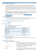
ENVIRONMENT VARIABLE The name of an environment variable, for example, PATH. ERROR NAME The name of an error, usually returned in the errno variable. Key The name of a keyboard key. Return and Enter both refer to the same key. Term The defined use of an important word or phrase. User input Commands and other text that you type. Variable The name of a placeholder in a command, function, or other syntax display that you replace with an actual value. [] The contents are optional in syntax.
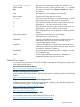
Contacting HP Before You Contact HP Be sure to have the following information available before you call contact HP: • Technical support registration number (if applicable) • Product serial number • Product model name and number • Product identification number • Applicable error message • Add-on boards or hardware • Third-party hardware or software • Operating system type and revision level HP Contact Information For the name of the nearest HP authorized reseller: • In the United States, see
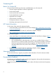
1 Installing the System This chapter provides information and procedures to install the server. Safety Information Use care to prevent injury and equipment damage when performing removal and replacement procedures. Voltages can be present within the server even when it is powered off. Many assemblies are sensitive to damage by electrostatic discharge (ESD).
Table 2 Installation Sequence Checklist (continued) Step Description Completed 6 Access the host console. 7 Power on the server. 8 Configure core I/O cards. 9 Boot the operating system. 10 Verify the server configuration. Unpacking and Inspecting the Server This section describes procedures you perform before installation. Ensure that you have adequately prepared your environment for the new server and received all the components you ordered.
Returning Damaged Equipment If the equipment is damaged, contact your HP customer service representative immediately. The service representative initiates appropriate action through the transport carrier or the factory and assists you in returning the equipment. Unloading the Server with a Lifter WARNING! Use caution when using a lifter. Because of the weight of the server, you must center the server on the lifter forks before lifting it off the pallet to avoid injury.
Figure 1 Removing and Replacing the Top Cover Replacing the Top Cover NOTE: Always replace the memory carrier assembly cover before replacing the top cover. To replace the top cover, follow these steps: 1. Ensure the memory carrier assembly cover is in place. 2. Ensure the cover release lever is in the unlocked position (Figure 1). 3. Align the tabs of the top cover with the corresponding slots in the chassis. Insert the tabs into the slots. 4.
3. Slide the memory carrier assembly cover toward the left side of the server to free it from the center of the chassis. Lift the cover off the chassis (Figure 2). Figure 2 Removing and Replacing the Memory Carrier Assembly Cover Replacing the Memory Carrier Assembly Cover To replace the memory carrier assembly cover, follow these steps: 1. Position the cover onto the opening above the memory carrier assembly. 2.
NOTE: A hot-swappable device does not require interaction with the operating system before the device is removed from or installed into the server. The dc power to the server does not have to be off to install or replace a hot-swappable power supply. Power Supply Loading Guidelines The supported configuration of the server requires a minimum of one power supply installed in either slot P0 or slot P1. You can install a second, optional hot-swappable power supply to provide 1+1 capability.
Figure 3 Removing and Replacing a Hot-Swappable Power Supply Removing and Replacing Hot-Swappable Disk Drive Fillers There are disk drive fillers installed for all slots that do not contain a disk drive. IMPORTANT: disk drive. For cooling purposes, always leave disk drive fillers in slots that do not contain a Removing a Hot-Swappable Disk Drive Filler To remove a hot-swappable disk drive filler, follow these steps: 1.
Figure 4 Removing and Replacing a Hot-Swappable Disk Drive Filler Replacing a Hot-Swappable Disk Drive Filler To replace a hot-swappable disk drive filler, perform the following: 1. Orient the disk drive filler so that the release tab is on the left side of the filler, and the airflow holes are on the right side of the filler. 2. Insert the filler into the slot guides, and slide the filler into the slot until it clicks into place and is fully seated.
TIP: When you receive an HP Integrity rx6600 server from HP, if you ever plan to add other SAS devices into the system, you should consider moving the SAS devices so they start in bay 1 going upwards instead of Bay 8 going downwards. Installing a Hot-Pluggable Disk Drive NOTE: The replacement disk drive must have the same product number as the disk drive that you replace. To install a hot-pluggable disk drive, follow these steps: 1. Use Figure 6 to determine the next available disk drive installation slot.
Figure 6 Disk Drive Slot IDs Installing a PCI/PCI-X/PCIe Card Figure 7 shows the PCI/PCI-X/PCIe slot identification and card divider locations. NOTE: Slots one through eight are full-length; slots nine and ten are short-length.
4 Slot 4 8 Slot 8 12 PCI/PCI-X/PXIe Card Dividers PCI/PCI-X/PCIe Configurations PCI/PCI-X/PCIe slots are numbered one through ten in the server (Figure 7). The following describes configuration requirements for slots one through ten on the PCI/PCI-X I/O backplane: • PCI-X slots 1 and 2 are reserved for use by the core I/O cards SAS core I/O card in slot 1 and Gigabit Ethernet LAN core I/O card in slot 2. Slots 1 and 2 are not hot-pluggable.
• Slots 7 and 8 are nonshared slots. The maximum speed for cards in slots 7 and 8 is PCI-X 133 MHz. • Slots 9 and 10 are shared slots. These two slots are limited by bus mode or frequency-related incompatibilities. IMPORTANT: Slots 9 and 10 on the PCI/PCI-X/PCIe I/O backplane have the same configuration limitations as slots 9 and 10 on the PCI/PCI-X/ I/O backplane. Table 3 lists the PCI/PCI-X card slot frequency and bus mode compatibility for shared slots.
5. Insert the PCI/PCI-X/PCIe card into the empty slot and exert firm, even pressure to seat the card in the slot. CAUTION: Ensure that you fully seat the card into the slot or the card can fail after power is reapplied to the slot. 6. 7. Connect all internal and external cables to the PCI/PCI-X card. Close the MRL. a. Rotate the MRL downward 90 degrees. b. Push the edge of the MRL down until it clicks into place on the PCI/PCI-X/PCIe card bulkhead. 8. 9.
4. Lift the memory carrier assembly out of the chassis (Figure 8). NOTE: To avoid damage to the handles, HP recommends rotating the handles inward and snapping them into place when servicing the system DIMMs or any time the carrier is out of the chassis. Before replacing the memory carrier, press the button to release the extraction handles. Use the handles to replace the memory carrier into the chassis.
3. Slide the memory carrier assembly into the chassis until it begins to seat into the socket located on the processor board. CAUTION: Do not apply excessive force when closing the extraction handles and seating the memory carrier assembly into the socket on the processor board. Manipulate the extraction handles with care; failure to observe these cautions can result in damage to the extraction handles and other server components. 4. 5.
Figure 9 Memory Carrier Assembly Figure 10 shows the memory carrier with the side cover open.
Figure 10 Memory Carrier Assembly with Side Cover Open Memory Installation Conventions Before installing memory, read and understand the following memory installation conventions: • Supported DIMM sizes and memory configurations • DIMM load order • DIMM slot IDs Supported DIMM Sizes and Memory Configurations The standard server configuration includes a 48-DIMM memory carrier, which contains one or two 24-DIMM memory boards. System DIMMs seat onto the memory boards.
Table 5 Memory Configuration Requirements Memory Carrier Type Memory Boards Installed Minimum Memory Configuration Maximum Memory Configuration 24-DIMM memory carrier (configuration 1) 1 X 24-DIMM memory board 2 GB (one quad: four 512-MB DIMMs) 192 GB (six quads: 24x8-GB DIMMs) 48-DIMM memory carrier (configuration 2) 2 X 24-DIMM memory boards 2 GB (one quad: four 512-MB DIMMs) 384 GB (12 quads: 48x8-GB DIMMs) Memory Load Order When installing memory, use a minimum of one quad of like-sized DIMM
Figure 11 48-DIMM Memory Carrier Board Slot IDs Memory Loading Rules and Guidelines Use the following rules and guidelines when installing memory: • Install DIMMs in quads. • Ensure that all DIMMs within a quad are identical. • Install quads in order of capacity from largest to smallest. For example, install all 2 GB quads before 1 GB or smaller quads, and install all 1 GB quads before 512 MB quads. • Side 0 must have equal or greater memory capacity than side 1.
a. b. c. If both sides of the memory carrier contain the same capacity of memory, install the next quad in side 0. If side 0 contains more memory capacity, even though it may have less DIMMs than side 1, install the next quad in side 1. If side 1 is full, install the remaining quads in side 0. Table 6 shows several examples of proper memory carrier loading order. IMPORTANT: The number in parenthesis indicates the order in which the quads are loaded.
2. Remove the memory carrier assembly. See “Removing and Replacing the Memory Carrier Assembly” (page 21). NOTE: To avoid damage to the handles, HP recommends rotating the handles inward and snapping them into place when servicing the system DIMMs or any time the carrier is out of the chassis. Before replacing the memory carrier, press the button to release the extraction handles. Use the handles to replace the memory carrier into the chassis. 3.
6. Install the DIMMs (Figure 12). a. Align the DIMM with the slot located on the memory board, and align the key in the connector with the notch in the DIMM. b. Push on each end of the DIMM firmly and evenly until it seats into the slot. c. Ensure that the extraction levers are in the fully closed position. Figure 12 Inserting a DIMM into the Memory Board Connector 7. Replace the memory carrier assembly side cover. a.
processor board is mounted onto a removable carrier tray, which is retained in the service bay by a hinged access door. WARNING! Ensure that the system is powered off and all power sources have been disconnected from the server prior to performing this procedure. Voltages are present at various locations within the server whenever an AC power source is connected. This voltage is present even when the main power switch is in the off position.
Figure 13 Removing the Processor Board Assembly Replacing the Processor Board Assembly To replace the processor board assembly, follow these steps: 1. Remove the processor board assembly. 2. Align the edges of the processor board assembly with the assembly guides in the chassis. 3. Slide the processor board assembly into the chassis until it begins to seat into the socket located on the midplane board. 4. Push the processor board access door upward until it locks into position. 5.
• 3P/6C (Three processors/six cores) • 4P/8C (Four processors/eight cores) If the server has fewer than the maximum number of dual-core processors installed, install the processors in the appropriate slot. WARNING! Ensure that the system is powered off and all power sources have been disconnected from the server prior to performing this procedure. Voltages are present at various locations within the server whenever an AC power source is connected.
2. Remove the memory carrier assembly. See “Removing and Replacing the Memory Carrier Assembly” (page 21). NOTE: You must remove the memory carrier assembly because it attaches directly to the processor board. 3. 4. Remove the processor board assembly. See “Removing and Replacing the Processor Board Assembly” (page 30). Open the processor cage (Figure 14). a. Grasp the processor cage handle and rotate the handle upward. b.
14. Close the processor cage (Figure 14). a. Grasp the processor cage handle and rotate the cage closure inward toward the rear of the assembly until it is completely closed. b. Push the handle down until it is flush with the cage. 15. Replace the processor board assembly. See “Removing and Replacing the Processor Board Assembly” (page 30). 16. Replace the memory carrier assembly. See “Removing and Replacing the Memory Carrier Assembly” (page 21). 17.
Figure 15 Processor Power Cable Figure 16 shows the processor socket lock/unlock mechanism and alignment post locations without a processor installed.
Figure 16 Processor Alignment Posts and Lock/Unlock Mechanism Figure 17 shows the processor lock/unlock mechanism location and the alignment holes with the processor installed.
Figure 17 Processor Alignment Holes and Lock/Unlock Mechanism Installing the Server into a Rack or Pedestal Mount This section provides instructions on how to install the server into a rack or pedestal mount. Installing the Server into a Rack The following information describes how to install the server into an HP rack or an approved non-HP rack. HP Rack HP servers that are installed into racks are shipped with equipment mounting slides.
HP Products. Follow the steps in this installation guide to determine where and how to install the server into the rack. The following are additional instructions for installing the server into the rack: 1. The cable management arm (CMA) is factory configured to mount on the left side of the server as viewed from the rear of the chassis. You must switch the CMA to a right-mount configuration. Mount the CMA on the right side of the server to ensure easy removal of the power supplies. 2.
the iLO 2 MP PC command, or the Power button is activated. In the off state, the power cords are not plugged in. Table 8 lists the server power states.
1. Locate the appropriate receptacle on the rear of the chassis. Plug the power cord into the receptacle. IMPORTANT: PWR 1. 2. If the server has one BPS, plug the power cable into the receptacle labeled Observe the following LEDs at two different intervals to ensure the server is in the standby power state: INTERVAL ONE After you plug the power cord into the server, the BPS flashes amber and an amber light is present on the hard disk drives.
1. 2. Obtain valid IP addresses for each LAN port you plan to activate. Connect the LAN cable from an available LAN port to a live connection on the network. Console Setup Setting up the console involves the following: 1. Determining the physical access method to connect cables. There are two physical connections to the Integrity iLO 2 MP: 2. • RS-232 serial port • iLO 2 MP LAN port Configuring the Integrity iLO 2 MP and assigning an IP address if necessary.
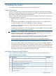
Table 10 Setup Checklist Step Action X Standard and Advanced 1 Preparation 1. Determine access method to select and connect cables. 2. Determine LAN configuration method and assign IP address if necessary. 2 Configure the iLO 2 MP LAN There are three methods to configure the LAN for iLO 2 MP access: • DHCP with DNS • ARP Ping • RS-232 serial port 3 Log on to the iLO 2 MP Log in to the iLO 2 MP from a supported web browser or command line using the default user name and password.
Figure 20 Setup Flowchart Preparation There are several tasks to perform before you can configure the iLO 2 MP LAN. • Determine the physical access method to select and connect cables. • Determine the iLO 2 MP LAN configuration method and assign an IP address if necessary. Determining the Physical iLO 2 MP Access Method Before you can access the iLO 2 MP, you must first determine the correct physical connection method. The iLO 2 MP has a separate LAN port from the system LAN port.
Figure 21 Server Rear Ports 1 2 iLO 2 MP RS-232 Serial Port (DB-9F to DB-9F cable) Connected to emulation terminal device (PC, laptop, or ASCII terminal) General Use Serial Port 3 USB 2.0 Ports 4 (any USB device) iLO 2 MP LAN Port 5 VGA Port No iLO 2 MP access; EFI only (10/100 LAN) (Printers, etc.) Use Table 11 to determine your physical connection method. Table 11 lists the appropriate connection method, required connection components, and connectors to the host console.
Once you have determined the iLO 2 MP access, you must determine how you will configure the iLO 2 MP LAN in order to acquire an IP address. There are three methods available. • DHCP/DNS • ARP Ping • RS-232 serial port Table 12 provides all the possible scenarios to consider. Use this table to help you select the appropriate LAN configuration method to obtain an IP address.
1. Obtain the factory-set host name from the iLO 2 MP Media Access Protocol (MAC) address label on the server. The default host name is 14 characters long, consisting of the letters mp followed by the 12 characters of the MAC address (example: mp0014c29c064f). This address is assigned to the iLO 2 MP core IO board. The core IO board has a unique MAC address that identifies the hardware on the network.
Table 13 ARP Ping Commands ARP Command Description arp -s This command assign the IP address to the iLO 2 MP MAC address. This ARP table entry maps the MAC address of the iLO 2 MP LAN interface to the static IP address designated for that interface. ping This command tests network connections. It verifies the iLO 2 MP LAN port is configured with the appropriate IP address.
IMPORTANT: Ensure you have a console connection through the RS-232 serial port or a network connection through the LAN to access the iLO 2 MP and use the LC command. To assign a static IP address using the LC command, follow these steps: 1. Ensure the emulation software device is properly configured. The terminal emulation device runs software that interfaces with the server. The software emulates console output as it would appear on an ASCII terminal screen and displays it on a console device screen.
2. Log in using the default the iLO 2 MP user name and password (Admin/Admin). TIP: For security reasons, HP strongly recommends you modify the default settings during the initial login session. See “Modifying User Accounts and Default Password” (page 50).
3. To setup user accounts: a. Access the MP Main Menu. b. Enter CM at the MP> prompt. c. Enter UC at the MP:CM> prompt and follow the prompts to modify user accounts. Setting Up Security For greater security and reliability, HP generally recommends that iLO 2 MP management traffic be on a separate dedicated management network and that only administrators be granted access to that network.
To interact with the iLO 2 MP through the web GUI, follow these steps: 1. Open a web browser and enter the host name or the IP address for the iLO 2 MP. 2. Log in using your user account name and password at the login page. (Figure 22). Figure 22 Web Login Page 3. Click Sign In. The Status Summary page (Figure 23) displays after login. Figure 23 Status Summary Page 1. 2. 52 Select the web interface functions by clicking the Function tabs at the top of the page.
3. Click the Remote Console tab. The remote console provides the following options to access the console: • A serial console that behaves similarly to the TUI of the following section • The virtual KVM console Help The iLO 2 MP web interface has a robust help system. To launch iLO 2 MP help, click the Help tab in the Display screen or click the ? at the top right corner of each page to display help about that page.
Powering Off and Powering On the Server This section provides information and procedures for powering off and powering on the server. For more information, see the operating system documentation. Server Power Button Figure 24 shows the server Power button. Figure 24 Server Power Button Power States The server has three power states: Standby power Plug the power cord into the appropriate receptacle on the rear of the chassis; the front panel Power button is not turned on.
Table 14 Power States Power States Power Cable Plugged into Receptacle Powered On with the iLO 2 MP PC Command, or Front Panel Power Button Pressed AC Voltage Applied DC Voltage Applied Standby power Yes No Yes No Full power Yes Yes Yes Yes Off No No No No NOTE: If the power restore feature is set to Always On through the iLO 2 MP PR command, the server can automatically power on to the full power state.
To power on the server using the iLO 2 MP, follow these steps: 1. Plug all power cables into the receptacles on the rear panel of the server. 2. Initiate a console session and access the MP Main Menu. 3. Enter CMto enable command mode. 4. Enter PC to use the remote power control command. 5. Enter ON to power on the server, and enter YES when prompted to confirm the action. 6. Start the operating system.
IMPORTANT: Do not store the files in this package on a SAS device. If you store these files on a SAS device and the update fails, these files will not be accessible. To update firmware, follow these steps: 1. Insert the HP IPF Offline Diagnostics and Utilities CD in the drive and boot to the EFI Shell. NOTE: You can also download the firmware image file and update utility from the HP website at: http://www.hp.com in the Driver Downloads section.
Another way for the firmware to be flashed is done without your knowledge. When mptutil is executed, and a SAS HBA is in any state other than ready or operational, mptutil immediately performs a firmware download boot. The firmware provided by you to do the firmware download boot is immediately flashed after the firmware download boot has completed. mptutil does this because the firmware only moves to the operational state if it is running from flash and not memory.
Starting the DRVCFG Utility To start the drvcfg configuration utility, follow these steps: 1. Select the EFI Shell from the console menu. 2. Enter drvcfg -s and press Enter. Using the DRVCFG Utility The configuration utility uses several input keys (F1, F2, HOME, END, and so on) that may not be supported by all terminal emulation programs. Each of these keys has an alternate key that performs the same function. Review the terminal emulation program documentation to verify which input keys are supported.
Figure 25 Accessed Screens in the drvcfg Utility DRVCFG Screens Adapter List Screen The Adapter List screen displays when the configuration utility is first started. This screen displays a scrolling list of up to 256 SAS controllers in the system, and information about each of them. Use the arrow keys to select a SAS controller, and press Enter to view and modify the selected SAS controller's properties. You can view and modify the SAS controller whether it is enabled or disabled.
Figure 26 Adapter Properties Screen Use the arrow keys to select RAID Properties, and press Enter to view the Select New Array Type screen. To access the following screens, use the arrow keys to select the screen, and press Enter on the appropriate field: • RAID Properties • SAS Topology • Advanced Adapter Properties The following are the descriptions for the Adapter Properties screen. Adapter Indicates the specific SAS Controller type.
Boot Support Specifies whether an adapter is eligible for configuration utility software control or is reserved for control by other software (Enabled BIOS & OS, Enabled BIOS Only, Enabled OS Only or Disabled). • Enabled BIOS & OS - SAS controller is controlled by both the BIOS and OS driver. • Enabled BIOS Only - SAS controller is controlled only by the BIOS. This setting may not be supported by all OS drivers. For example, it is not possible to disable an adapter in a Windows driver.
2. To create the array after the volume is configured, press C. The system prompts you to save changes, which creates the array. During the creation process, the utility pauses. You are then taken back to the Adapter Properties screen. The following are the descriptions for the Create New Array screen. Array Type Indicates the type of array being created. Array Size Indicates the size of the array in MegaBytes. Bay Displays the bay in which devices are located.
Wrg Type Device is not compatible for use as part of an IM array. Too Small Disk is too small to mirror existing data. Max Dsks Maximum # of disks allowed for this type of Array reached and/or Maximum # of total IM disks on a controller reached. No SMART Disk doesn't support SMART, cannot be used in an RAID array. Wrg Intfc Device interface (SAS) differs from existing IM disks. Pred Fail Indicates whether device SMART is predicting device failure (Yes, No).
provided the array is made up of 5 disks or fewer. This field is grayed out under the following conditions: Drive Status • The device does not meet the minimum requirements for use in an IM array. • The array already has a hot spare. • The array is made up of the maximum number of devices (6). • The device isn't large enough to mirror existing data on the primary. The hot spare drive must be greater than or equal to the size of any drive in any IM volume.
The Manage Array screen enables you to perform the following actions: Manage Hot Spare To display a Hot Spare Management screen that has the same layout as the Create New Array screen, press Enter on Manage Hot Spare. This field is grayed out under the following conditions: • The array is inactive. • The array is at its maximum number of devices. • Non-IR firmware is used. • IR is disabled. The array is inactive.
• Discard changes and reboot • Exit the Configuration Utility and Reboot CFGGEN Utility The cfggen utility is a command line utility that runs in the Linux, EFI, and Windows Pre-Installation (WinPE) environments. It is a minimally interactive program that you execute from a command line prompt, or a shell script. The results from invoking this utility are communicated through the program status value that is returned when the program exits.
• An IM array must have exactly two disks. • A hot spare disk cannot be created without at least one IM volume already created. • The utility does not allow adding a hot spare disk of type different from disk types in any of the volume. • With the AUTO command all drives used are the same type as the first available disk found, and the size is limited to the size of the smallest disk. CFGGEN Commands Using the CREATE Command The create command creates IM volumes on the SAS controller.
Operation When AUTO creates an IM volume, the first disk found is assigned as the primary disk drive. If the controller is allowed to resync the disk drives, the data on the primary disk drive is available by accessing the newly created volume. Reply Yes if you want to complete the creation. HOTSPARE The HOTSPARE command creates a hot spare disk drive. The hot spare drive is added to hot spare pool 0.
The latest firmware, drivers, utilities, software, and documentation for HP Integrity servers are available on the support page of the HP website at http://www.hp.com/support/itaniumservers. Connecting External Storage IMPORTANT: Not all OSs support external drives. To connect external storage, follow these steps: 1. Power off the server. 2. Connect an external SAS cable to the external port of the controller.
IMPORTANT: Both saupdate.efi and the firmware image file must be located in the same directory. If they are not, copy them both to the EFI partition. Run the saupdate.efi using the fs0:\> saupdate command. • 1. 2. 3. 4. If you are not using the Offline Diagnostic CD: Download the SA EFI update utility saupdate.efi and copy it to the EFI partition. Download the firmware and copy it to the EFI partition. Boot the system to the EFI Shell and change directories to the EFI partition. Run the saupdate.
Replace CYBORG234.BIN with the name of your firmware file. The following screen displays: ************************************************************* Smart Array Offline Firmware Update Utility Version: 1.04.12.00 (C) Copyright 2004 Hewlett Packard Development Company L.P. ************************************************************* Updating controller in Seg: 1, Bus: 51, Dev: 4, Func: 0 Current firmware version 1.92 Percentage completed: 100% Activating firmware now, this may take several minutes.
HELP or ? Use HELP or ? to display usage text, program version number, and build date: Enter: saupdate HELP or saupdate ? Error Messages The following is a list of error messages under various situations: • When keyword LIST or UPDATE is misspelled or extra parameters are specified: Error: Syntax Error Usage: saupdate LIST or saupdate UPDATE [ • all ] When the controller ID in the saupdate UPDATE command is not correct: No matching controller found • When a firmware file does not exist in the saupdate
4. 5. Select OK and press Enter to continue. From the main menu, select Maintain Firmware and press Enter. Figure 29 EBSU Main Menu 6. 7. 8. In the Maintain Firmware screen, use the tab key to scroll down to the Device section. Use the down arrow key to scroll down to the Smart Array Controller item in the list. Press Enter to display detailed information about the device. Figure 30 EBSU Maintain Firmware Screen EBSU displays the firmware update screen for the selected device.
Figure 31 EBSU Maintain Firmware Update Screen 9. Compare the two version numbers and perform one of the following options: • If the number in the first column is the same or higher than the number in the second column, your installed firmware is current. You do not need to update the firmware for this device! You can exit EBSU and quit this procedure.
Guide at I/O Cards and Networking Software on the HP website at http://www.hp.com/go/ integrity-iocards-docs. Click the link for your HP-UX version. Support guides are listed alphabetically in the “User guide” section. Comparing the Utilities Table 17 lists the supported features and procedures for the ACU and ORCA utilities. NOTE: Yes in the appropriate column indicates that the feature or procedure is supported, while No indicates that the feature or procedure is not supported.
2. At the ORCA prompt: • If you are connected using a headless console, press the Esc+8 combination. • Otherwise, press F8. The ORCA Main Menu displays, enabling you to create, view, or delete a logical drive. Figure 32 ORCA Main Menu Creating a Logical Drive Using ORCA To create a logical drive using ORCA, follow these steps: 1. Select Create Logical Drive. The screen displays a list of all available (unconfigured) physical drives and the valid RAID options for the system. 2.
Click the link for your HP-UX version. Support guides are listed alphabetically in the “User guide” section. Installation Troubleshooting This section provides basic server troubleshooting information to help you diagnose common issues that can occur during server installation. Troubleshooting Methodology The server was tested prior to shipping. Failures encountered during installation can be due to damage that occurred in transit. Reseating connectors can solve problems that result from rough handling.
Table 18 Server Power Button Functions (continued) Action Reaction Server Power Button Function When Server is Off Press and hold the Power button for one to three seconds System power turns on. Server Does Not Power On The server Power button on the front panel operates differently depending on how long you press and hold the button, and on what the system is doing when the button is pressed. You must be aware of the Power button functionality to properly troubleshoot the system.
Intermittent Server Problems You can usually trace intermittent problems that occur during installation to power source problems, a loose connector, or some other hardware problem. If you are experiencing intermittent problems, follow these steps: 1. Check iLO 2 MP logs and analyze the problem. Determine if there is more than one symptom and if the problem is random. 2. Verify that the AC power source is stable. 3. Reseat all rear panel connectors. 4. Reseat all hot-swappable fans and power supplies. 5.
3. 4. 5. 6. 7. Select Itanium-based servers from the Server category. Select your server from the servers listed. Select your operating system. Select the firmware category you want to download. Download the firmware to a CD. Installing the Latest Version of the Firmware on the Server To install the latest version of the firmware on the server, follow these steps: 1. Start a server console session. See Section : “Console Setup” (page 42). 2.
b. c. d. 3. 4. 5. 6. 82 Enter info sec to display the server security settings on the screen. The TPM is disabled by default. Enter secconfig to display a list of configurable security settings. Enter secconfig tpm on to enable the TPM. Reset the server. Boot the operating system. Restore the former TPM settings to the new TPM. See the HP-UX operating system documentation for more information. Back up the TPM security information. See the HP-UX operating system documentation for more information.
Index Symbols 48-DIMM memory carrier assembly see memory 8 Internal Port SAS HBA controller, 56 A accessing the host console using SMASH SM CLP, 53 using vKVM/IRC, 53 with the TUI CO command, 53 accessing the iLO 2 MP using the web browser, 51 acu utility, 77 ARP ping commands, 47 using to configure the iLO 2 MP LAN, 47 using to set the IP address, 48 B bulk power supplies (BPS), 39 C cable SAS cable part numbers, 70 cell board, 39 cfggen utility, 67 CM command, 55, 56 command mode see CM command configu
48-DIMM memory carrier assembly slot IDs, 26 installation conventions, 25 installing, 28 load order, 26 load order, 24-DIMM memory carrier board, 26 load order, 48-DIMM memory carrier assembly, 26 supported DIMM sizes, 25 memory carrier assembly removing, 21 replacing, 22 memory extender board see memory carrier assembly mptutil utility, 56 restrictions, 33 processor board see processor board assembly processor board assembly removing and replacing, 31 O safety information, general, 9 sas controller, 56