HP Integrity rx6600 Rack to Pedestal Conversion Guide HP Part Number: AB464-9009A Published: November 2006 Edition: 1
© Copyright 2006 Hewlett-Packard Development Company, L.P. The information contained herein is subject to change without notice. The only warranties for HP products and services are set forth in the express warranty statements accompanying such products and services. Nothing herein should be construed as constituting an additional warranty. HP shall not be liable for technical or editorial errors or omissions contained herein.
Table of Contents About This Document.........................................................................................................5 Intended Audience....................................................................................................................................5 Document Organization.............................................................................................................................5 Typographic Conventions..............................................
List of Figures 2-1 2-2 2-3 2-4 2-5 2-6 2-7 2-8 3-1 3-2 3-3 3-4 Server on Pallet................................................................................................................................9 Pallet Ramp....................................................................................................................................10 Raised Server.................................................................................................................................
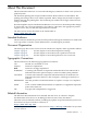
About This Document This document describes how to convert the HP Integrity rx6600 server from a rack system to a pedestal system. The document printing date and part number indicate the document’s current edition. The printing date changes when a new edition is printed. Minor changes may be made at reprint without changing the printing date. The document part number also changes when extensive changes are made. Document updates may be issued between editions to correct errors or document product changes.
Publishing History This table lists the publishing history of this document. Document Manufacturing Part Number Publication Date AB464-9009A November 2006 HP Encourages Your Comments HP encourages your comments concerning this document. We are committed to providing documentation that meets your needs. Send any errors found, suggestions for improvement, or compliments to: feedback@fc.hp.
1 Important Warnings Electricity Electrical Grounding WARNING! For your safety always connect the equipment to a grounded wall outlet. Always use a power cord with a properly grounded plug, such as the one provided with the equipment, or one in compliance with your national safety standards. This equipment can be disconnected from the power by removing the power cord from the power outlet. This means the equipment must be located close to an easily accessible power outlet.
2 Rack to Pedestal Conversion The procedures for converting your rack system to a pedestal system are as follows: NOTE: 1. 2. 3. 4. 5. 6. If your server has not previously been installed in a rack, begin with Step 3. Remove the system from its rack enclosure. Remove the rack components from the server. Install the caster wheels. Install the bezel cover. Install the pedestal kit side components. Install the pedestal kit top.
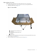
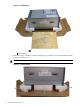
Pallet Installation Procedure Follow these steps to attach the caster wheels when the server is on the pallet. 1. Unpack the shipping carton, removing the accessory tray and pedestal kit box. 2. Unfold the bottom tray. See Figure 2-1 Figure 2-1 Server on Pallet 3 Side Bottom Foam Cushion (one on each side) 2 Front and Rear Bottom End Foam Cushions 3 Bottom Tray Carefully, pull out the Side Bottom Foam Cushions from the right and left sides, and set aside for later use.
Figure 2-2 Pallet Ramp Pallet Ramp Raise the server, one side at a time, by lifting it up, and placing it on the Side Bottom Foam Cushions. See Figure 2-3. 1 5. WARNING! Be careful when lifting the server as it is heavy.
6. 7. 8. Pull out the Front and Rear Bottom End Foam Cushions. See Figure 2-3. Locate the attachment points for the left caster wheels by finding the rivets that are the same distance part as the holes in the caster wheel assembly. Align the holes in the caster wheel assembly below the rivets on the server. Figure 2-4 shows the left side caster wheels in place. Figure 2-4 Caster Wheels on Raised Server 1 2 Rear Left Caster Wheel 2 Front Left Caster Wheel 9.
11. Place the ramp on the front of the pallet. See Figure 2-5 CAUTION: TIP: Do not roll the server off the pallet without first securing the ramp to the pallet. The ramp may also be attached to the rear of the pallet. Figure 2-5 Ramp Attached to Pallet Pallet Ramp 12. Secure the ramp in place by inserting the screws into the pre-drilled holes. See Figure 2-6. The ramp is secure when the screws are fully inserted, flush with ramp.
Figure 2-6 Ramp Attachment Detail CAUTION: Screws which are not fully inserted may hook the caster wheels or the bottom of the server. 13. Roll the server off the pallet. See Figure 2-5. Floor Installation Procedure Follow these steps to attach the caster wheels when the sever is on the floor. 1. Turn the server onto its right side. WARNING! CAUTION: handles. 2. 3. 4. Be careful when lifting the server as it is heavy.
CAUTION: attached. The server will be slightly more difficult to turn on its side with the caster wheels Figure 2-7 Caster Wheels on the Server Installing the Bezel Cover Follow these steps to install the bezel cover. 1. Attach the bezel cover to the front of the server starting from the server left. 2. Push the bezel cover into place against the server right side (see Figure 2-8) until the tabs on the bezel cover snap into place.
Figure 2-8 Attaching the Bezel Cover Installing the Pedestal Kit Sides The pedestal kit sides are labeled LEFT and RIGHT. Follow these steps to attach the pedestal kit sides. 1. Align the holes in the pedestal kit side with the rivets on the side of the server. NOTE: One of the holes in the pedestal component contains the locking mechanism. This will make the hole appear partially blocked. 2. 3. Hold the pedestal side flush against the server.
3 Pedestal to Rack Conversion The procedures for converting your tower system to a rack system are as follows: 1. Power down the server and remove all cables. 2. Remove the pedestal kit top. 3. Remove the pedestal kit sides. 4. Remove the bezel cover. 5. Remove the caster wheels. 6. Install the server into the rack. TIP: Removal of the pedestal kit is best performed on a raised surface, as access to the bottom of the server is required to complete the procedure.
Figure 3-1 Server Rear 1 2 1 2 Finger Grips Thumb Screws Removing the Pedestal Sides Follow these steps to remove the pedestal sides. 1. Looking from the bottom locate the lock release slot. 2. Insert a regular (flat head) screwdriver into the lock release slot. See Figure 3-2. 3. Slide the screwdriver into the lock release slot. See Figure 3-4. 4. Pull back on the side. 5. Once the pedestal side has moved about 1/4 inch, the lock will release, and the screwdriver can be removed. 6.
Figure 3-2 Lock Release Slot 1 1 Lock Release Slot Flip the procedure on the other side. Removing the Bezel Cover To remove the bezel cover: 1. Release the locking tabs behind the right corners of the bezel cover. See Figure 3-3. 2. Pull the cover away from the server. Figure 3-3 Locking Tab 1 1 Locking Tab Removing the Caster Wheels 1. Turn the server onto its right side. WARNING! CAUTION: handles. Be careful when lifting the server as it is heavy.
Turn the server over onto the left side and repeat the process for the right side wheels. Figure 3-4 Removing the Caster Wheels 1 1 Metal Locking Tabs Installing the Server into the Rack For rack installation procedures refer to the server installation guide, users' guide, and the Rack System /E User's Manual at: http://www.hp.com under Enterprise Rack & Power Products, or other documentation that came with your rack kit.
Index B Z bezel cover installing, 14 removing, 18 zinc whiskers (see metallic particulate contamination) C caster wheels installing, 8 E electricity grounding, 7 static, 7 L locking tab, 18 M metallic particulate contamination, 7 P pedestal bottom removing, 16 pedestal feet removing, 18 pedestal sides installing, 15 removing, 17 pedestal top installing, 15 removing, 16 R rack component removal, 8 installation, 19 server removal, 8 S server powering down, 8, 16 static electricity (see electricity,
*AB464-9009A* Printed in the US