
HP Integrity rx7620 Server - User Service Guide, Sixth Edition
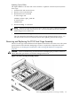
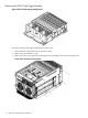
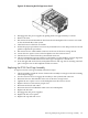
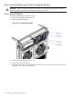
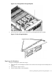
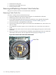
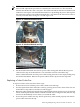
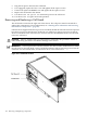
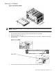
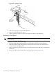

Figure 6-30 Removing the PCI Cage Access Panel
4. Disengage the PCI power supplies by pulling them out approximately 1.5 inches.
5. Remove PCI fans.
6. Disconnect the PCI-X OLR ribbon cable from the PCI backplane. The connector is located
on the cell board side of the system.
7. Label and remove all PCI-X card cables.
8. Follow the proper procedures to remove any mounted PCI-X cards. Keep track of each card
path for replacement procedures.
9. Disconnect the two cable bundle connectors at the rear of the mass storage board.
10. Loosen the two captive screws on the backplane near the extractor levers.
11. Pull the levers to release from the system board connector.
12. The PCI-X backplane support wall has a grab handle. Use this handle to assist in alignment
for removal. The outside of the PCI fan card cage is designed as a handle also.
13. From the right side of the chassis, manipulate the PCI card cage free of retaining stand-off
pins. Tilt up the rear of the backplane and lift to remove.
Replacing the PCI-X Card Cage Assembly
To replace a PCI-X card cage assembly, follow these steps:
1. Tilt the assembly toward the chassis. Position the assembly at an angle so that the retaining
stand-off pins engage.
2. Use the extractor levers to engage the assembly to the system board connector.
3. Reconnect the two cable bundles at the rear of the mass storage board.
4. Tighten the two captive screws on the backplane near the extractor levers.
5. Replace all PCI-X cards in their proper slots.
6. Reconnect all PCI-X card cables.
7. Reconnect the PCI-X OLR ribbon cable to the PCI-X backplane.
8. Replace the PCI fans.
9. Re-engage the PCI power supplies.
10. Replace the PCI access panel.
11. Replace the top and side covers.
Removing and Replacing the PCI-X Card Cage Assembly 123