
HP Integrity rx7620 Server - User Service Guide, Sixth Edition
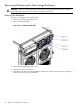
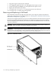
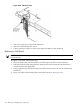

5. Plug the fan power cable into the cell board.
6. If so equipped, replace the CPU cover and tighten all the captive screws.
7. If removed, replace the DIMM cover and tighten all the captive screws.
8. Replace the cell board in the cabinet.
9. Use the MP:CM> PE option C to return 48V power to the cell board
10. Use the MP:CM> bo option to boot the partition.
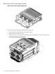
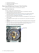
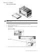
Removing and Replacing a Cell Board
The cell board is located in the right side of the chassis. The cell power must be turned off to
replace this component. For more information, see “Shutting Down nPartitions and Powering
Off Hardware Components ” (page 96).
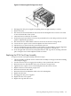
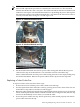
Cell boards are shipped with all four processors installed. Should the old cell board to be replaced
have fewer processors than the new cell board, you will have to remove processors to match
what was installed on the old cell board. You must transfer the DIMMs from the old cell board
to the new cell board.
CAUTION: Observe all ESD safety precautions before attempting this procedure. Failure to
follow ESD safety precautions can result in damage to the server.
IMPORTANT: The SCSI parameters and the real time clock data stored in NVRAM are lost when
the cell board is removed. Make a note of all SCSI parameters before removing power from the
cell board. For more information, see Matterhorn Service Note A6093A-07A.
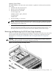
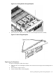
Figure 6-37 Cell Board Location
128 Removing and Replacing Components