
HP Integrity rx7620 Server - User Service Guide, Sixth Edition
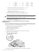

15. Locate the peep hole on the left side of the CPU turbo-cooler by slightly rotating the fan
blades.
WARNING! When unlocking the ZIF socket, do not exceed the one half turn
counter-clockwise. Damage to the socket will occur, requiring replacement of the cell board.
16. Insert the 2.5 mm hex driver between the fan blades, through the peep hole, and turn the
ZIF socket lock screw one half turn counter-clockwise to unlock the CPU from the socket.
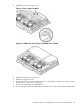
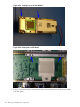
17. Lift the CPU/turbo-cooler/power pod assembly straight up and off the cell board.
NOTE: If the socket will not be populated with a replacement processor module, place the ZIF
socket cover over the ZIF socket. Tighten the four screws in an X pattern until secure.
Replacing the Processor
CAUTION: Avoid removing any VRMs to connect the CPU power pod and turbo-cooler cables
into the cell board connectors.
NOTE: CPU load order must be maintained when adding CPUs to the cell board. Always load
CPU socket 0 first.
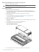
To replace the processor, follow these steps:
1. If the CPU 0 ZIF socket is not exposed, remove the ZIF socket pin cover from the cell board.
2. Ensure that the cell board ZIF socket is in the unlocked position.
3. Remove the CPU module from its packaging.
4. Remove the CPU module pin cover and inspect the pins for any damage.
NOTE: Carefully remove pin cover to avoid any damage to the pins.
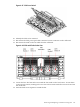
5. Slide the load screw sequencer toward the turbo-cooler to expose the ZIF socket peep hole
through the turbo-cooler.
6. Lower the CPU module onto the ZIF socket making sure it is held level to the board until
the pins engage the ZIF socket.
7. Using a 2.5 mm hex driver through the peep hole, turn the ZIF socket lock/unlock screw
one half turn to lock the CPU into place.
CAUTION: Do not exceed one half turn clockwise when locking the CPU into the ZIF
socket. Damage to the ZIF socket will occur, requiring the cell board to be replaced.
NOTE: Ensure that the ZIF socket is fully locked. Use a 2.5mm hex wrench to lock the ZIF
socket. Check that the CPU module housing is level and shifts slightly right when locking
the ZIF socket.
8. Slide the load screw sequencer away from the turbo-cooler.
9. Tighten the four T15 screws on the sequencer in an X pattern, turning each screw two to
three turns until all screws are secure.
NOTE: The processor screws do not need to be torqued. The processor is properly secured
when the screws reach the bottom on the socket frame.
10. Tighten the four captive screws on the power pod in an X pattern until secure.
11. Connect the turbo-cooler fan cable to the cell board connector.
148 Removing and Replacing Components