
HP Integrity rx7620 Server - User Service Guide, Sixth Edition
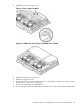

12. Reconnect the CPU power cable to the cell board connector.
13. Replace the processor cover and tighten the captive screws.
NOTE: New cell boards housing the new IPF processors will require new air baffles. For
more information, see “Installing the VRM Cover (AB388-00002) and Door Opener
(AB388-00003)” (page 144).
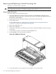
14. Position the DIMM cover in place.
15. Tighten the four captive screws to secure the DIMM cover.
16. Install the cell board in the server.
17. Replace covers.
18. Power on the server.
19. Power on the nPartition. See Appendix D.
Installing Dual-Core CPUs (A9767A)
There are three additional components required when replacing a CPU with a dual-core CPU.
If only one CPU module is installed on the cell board, a terminator must be installed in CPU
socket 2.
• Dual-core CPU (A9767-04012)
• Sequencer fan assembly (A9767-04007)
• CPU cover
All CPU sockets must be empty before proceeding.
CAUTION: Avoid removing any VRMs to connect the CPU power pod and turbo-cooler cables
into the cell board connectors.
NOTE: CPU load order that must be maintained when adding CPUs to the cell board. Always
load CPU socket 0 first.
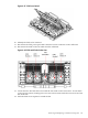
To install a dual-core CPU, follow these steps:
1. Remove the dual-core CPU from its packaging.
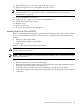
2. Route the red and black cables into the groove in the back of the CPU module toward the
appropriate power connector on the cell board.
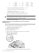
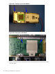
3. Lower the CPU module onto the socket making sure it is held level to the board.
4. Align the locating pins on the underside of the module onto the guide holes on the cell board
socket rails.
Removing and Replacing a Central Processing Unit 149