
HP Integrity rx7620 Server - User Service Guide, Sixth Edition

AB439A and AB548A Processor Stepping Information
IMPORTANT: Intel updated A2 stepping of the Itanium 2 AB439A and AB548A processors.
Intel is no longer providing A1 stepping processors. HP and its customers will have to gradually
transition to A2 stepping processors.
For approximately two years (June 2005 - June 2007), A1 stepping processors were replaced with
A1 stepping processors and A2 stepping processors were replaced with A2 stepping processors.
Once A1 processor exchange parts are no longer available, the parts must be replaced with A2
processors and the system firmware updated if necessary.
How to Identify an A1 Stepping processor from an A2 Stepping processor
Table 6-5 Processor Stepping Comparisons
FRU-ID P/NStepping NumberDescriptionFRU Exchange P/N
AB439-04001A11.5GHz 4MBA6913-69009
AB548-04001A11.6GHz 6MBA6913-69011
AB439-04004A21.5GHz 4MBA6913-69014
AB548-04004A21.6GHz 6MBA6913-69015
Mixing A1 and A2 Stepping Processors
A1 and A2 processors may be mixed on the same cell board with A2-compatible firmware. Cell
boards with A1 processors may be mixed with cell boards with A2 processors within the same
partition.
CAUTION: Minimum Firmware Version must be 3.3 with A2 processor cell board(s) or the
system does not boot. If the logical firmware download order is not followed, unpredictable
results can also occur.
Related Information
• On the WTEC server, see the WTEC newsletter of Current Issues Communications Relative to
the Intel Itanium 2 Madison 9M Processor and Upcoming Firmware (#319).
• Service Notes for the firmware releases with A2 Stepping processor support. Firmware
Release notes are summarized in the service note for the HP Integrity rx7620.
• ReadMe flyers are included with the Add-On A2 processor parts and GSO replacement parts
indicating the minimum level of firmware required.
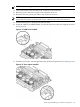
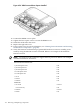
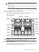
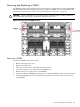
CPU Installation Procedures
All CPU sockets must be empty before proceeding.
CAUTION: Avoid removing any VRMs to connect the CPU power pod and turbo-cooler cables
into the cell board connectors.
NOTE: CPU load order must be maintained when adding CPUs to the cell board. Always load
CPU socket 0 first.
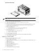
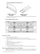
To install new CPUs, follow these steps:
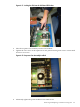
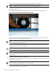
1. If the CPU 0 ZIF socket is not exposed, remove the ZIF socket pin cover from the cell board.
2. Ensure that the cell board ZIF socket is in the unlocked position.
3. Remove the CPU module from its packaging.
Removing and Replacing a Central Processing Unit 153