
HP Integrity rx7620 Server - User Service Guide, Sixth Edition
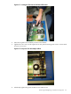
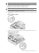

4. Remove the CPU module pin cover and inspect the pins for any damage.
NOTE: Carefully remove pin cover to avoid any damage to the pins.
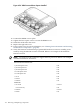
5. To expose the ZIF socket peep hole through the turbo-cooler, slide the load screw sequencer
toward the turbo-cooler.
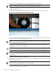
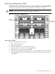
6. Rotate the fan to expose the ZIF socket peep hole location. See Figure 6-53 (page 154).
Figure 6-53 ZIF Socket Lock/Unlock Peep Hole Location
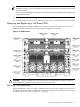
7. Lower the CPU module into the ZIF socket making sure it is held level to the board, until
the pins on the CPU engage with the ZIF socket.
NOTE: The new CPU power pod is slightly hinged. Ensure that the CPU assembly is level
prior to lowering it onto the cell board.
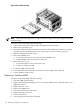
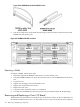
8. Using a 2.5 mm hex driver through the peep hole, turn the ZIF socket lock/unlock screw
one half turn to lock the CPU into place.
CAUTION: Do not exceed one half turn clockwise when locking the CPU into the ZIF
socket. Damage to the ZIF socket will occur, requiring the cell board to be replaced.
NOTE: Ensure that the ZIF socket is fully locked. Use a 2.5mm hex wrench to lock the ZIF
socket. Check that the CPU module housing is level and shifts slightly right when locking
the ZIF socket.
9. Push the load sequencer away from the fan.
10. Tighten the four CPU module screws in an X pattern, turning each screw two to three turns,
until all screws are secure.
NOTE: The processor screws do not need to be torqued. The processor is properly secured
when the screws reach the bottom on the socket frame.
11. Alternately tighten the two power pod screws until secured. Ensure that the entire CPU
module is seated level in the cell board.
154 Removing and Replacing Components