
HP Integrity rx7620 Server - User Service Guide, Sixth Edition

NOTE: Do not overtighten the screws. Damage can occur to the cell board.
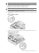
12. Connect the turbo-cooler fan cable to the connector on the cell board.
13. Route the power cable, left or right, to the cell board connector.
14. Reconnect the CPU power pod cable to the cell board connector.
NOTE: Due to space constraints, it may be necessary to use a tool to assist with inserting
CPU 0 and CPU2 power pod and turbo-cooler cables into the cell board connectors.
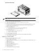
15. Install remaining CPUs, keeping load order in mind.
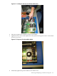
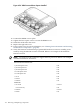
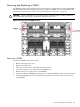
16. Install the VRM cover (AB388-00002), onto the left side of the cell board. Tighten the screw.
See Figure 6-54.
Figure 6-54 VRM Cover Installed
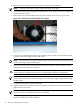
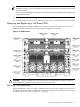
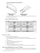
17. Install the door opener, onto the right side of the cell board. Tighten the screw. See Figure 6-55.
Figure 6-55 Door Opener Installed
Removing and Replacing a Central Processing Unit 155