
HP Integrity rx7620 Server - User Service Guide, Sixth Edition
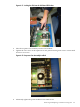
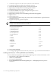
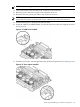
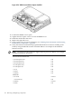
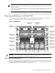
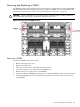
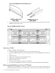

Figure 6-56 VRM Cover and Door Opener Installed
18. Position the DIMM cover in place.
19. Tighten the four captive screws to secure the DIMM cover.
20. Install the cell board in the server.
21. Replace the right side cover.
22. Power on the server. For more information, see “Shutting Down nPartitions and Powering
Off Hardware Components ” (page 96).
23. Verify the firmware and hardware programmable hardware revisions in standby power
mode by using the MP:CM>SYSREV command. Below is an example of the minimum
firmware version.
NOTE: Firmware must be updated to support the new processors. Below is an example
of minimum Firmware Version 3.3.
PROGRAMMABLE HARDWARE
1.002System Backplane GPM
1.002System Backplane FM
1.002System Backplane OSP
2.000PCI-X Backplane LPM
1.000PCI-X Backplane HS
2.008Core IO
1.002Cell LPM
1.007Cell PDHC
FIRMWARE:
A.006.012Core IO MP
1.009Event Dictionary
A.003.023Cell PDHC
1.025Cell SFW
156 Removing and Replacing Components