
HP Integrity rx7620 Server - User Service Guide, Sixth Edition
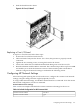
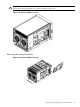
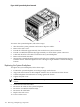


Table 6-6 Default Configuration for MP Customer LAN (continued)
255.255.255.0Customer LAN Subnet Mask
192.168.1.1Customer LAN Gateway
This procedure (Command menu, LC command) configures the MP customer LAN network
settings from the MP Command menu.
1. Connect to the server complex MP and enter CM to access the Command menu.
To connect to the MP, use Telnet if possible.
If a MP is at its default configuration (including default network settings), connect to it using
either of these methods:
• Establish a direct serial cable connection through the MP local RS-232 port.
• Access a PC or workstation on the same subnet as the MP, modify its network routing
tables to include the default customer LAN IP address, then Telnet to the MP.
To modify networking and connect, follow these steps:
1. Access a PC or workstation on the MP subnet.
2. Modify the network routing tables for the PC or workstation by using the
route add 192.168.1.1ClientName
command, where
ClientName Is the network name of the PC or workstation.
From a PC command prompt, enter route add 192.168.1.1ClientName
On an HP-UX workstation, log in as root and use the /usr/sbin/route add
192.168.1.1 ClientName command:
After reconfiguring the MP networking, remove these network routing table changes
with the route delete command.
3. To confirm the new network connection to the MP, enter the ping 198.168.1.1
-n 2 command.
4. To connect to the MP, use the telnet 192.168.1.1 command from the PC or
workstation.
2. From the MP Command menu, enter LS to list the current network settings, and, if needed,
use the LC command to reconfigure the network settings for the MP.
The LC command enables modifications to the customer LAN and/or the private LAN
configuration.
Cancel all changes to the MP LAN configuration at any time by replying Q to any of the LC
command prompts.
3. Ensure that the MP networking configuration is correct.
Removing and Replacing the System Backplane
The system backplane is located in the left side of the chassis. Before attempting to remove or
replace this component, you must remove all system power.
164 Removing and Replacing Components