
HP Integrity rx7620 Server - User Service Guide, Sixth Edition
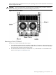
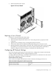
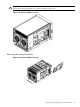
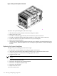
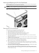
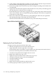
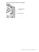


Figure 6-68 System Backplane Removed
To remove the system backplane, follow these steps:
1. Shut down the system partitions and remove all power cables.
2. Remove the side covers.
3. Extend all cell boards approximately four inches from system connectors.
4. Extend core MP/SCSI I/O board(s) approximately 1.5 inches from system connectors.
5. Label and disconnect all cables connected to the system backplane.
6. Remove hard attach brackets.
7. Support the system backplane and loosen the Jack screw until the system backplane releases
from the chassis. Tilt the backplane back to a 45-degree angle and lift it out from the hinged
bottom.
Replacing the System Backplane
To replace the system backplane, follow these steps:
1. Position the system backplane at a 45 degree angle in the chassis.
2. Align tabs at the bottom of the backplane with the slots on the bottom of the chassis.
3. Tilt the backplane forward until it is resting against the chassis.
4. Tighten the Jack screw.
NOTE: Watch for system board flex. Overcompression will break the board and render it
useless.
5. Install the hard attach brackets.
6. Reconnect all cables on the system backplane.
7. Reconnect core MP/SCSI I/O board(s).
8. Reconnect all cell boards.
9. Replace the side covers.
10. Power on the server.
166 Removing and Replacing Components