
HP Integrity rx7620 Server - User Service Guide, Sixth Edition

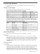
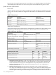
power rating of the bulk power supplies. This number can safely be used to size AC circuits
and breakers for the system.
3. Typical maximum power is the input power measured at the AC input expressed in Watts
and Volt-Amps, and the measured maximum worst case power consumption. This number
represents the largest power consumption for the server under laboratory conditions, using
aggressive software applications designed specifically to work the system at maximum loads
and power consumption.
DC-Powered Systems
DC-powered systems must be powered by a -48 VDC Telco power source. Follow your site-specific
procedures for connecting the power and return lines to the server.
Environmental Specifications
This section provides the environmental, power dissipation, noise emission, and airflow
specifications for HP Integrity rx7620 Servers.
Temperature and Humidity
The cabinet is actively cooled using forced convection in a Class C1-modified environment.
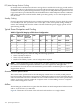
Operating Environment
The system is designed to run continuously and meet reliability goals in an ambient temperature
of 5° to 35° C at sea level. The maximum allowable temperature is derated 1° C per 1000 feet of
elevation above 5000 feet above sea level up to 30° C at 10,000 feet. For optimum reliability and
performance, the recommended operating range is 20° to 25° C.
Environmental Temperature Sensor
To ensure that the system is operating within the published limits, the ambient operating
temperature is measured using a sensor placed near the chassis inlet, between the cell boards.
Data from the sensor is used to control the fan speed and to initiate system overtemp shutdown.
(For more details, see the platform management section.)
Non-Operating Environment
The system is designed to withstand ambient temperatures between -40° to 70° C under
non-operating conditions.
Cooling
Cell Section Cooling
The cabinet incorporates front to back airflow across the cell boards and system backplane. Two
150 mm fans, mounted externally on the front chassis wall behind the cosmetic front bezel, push
air into the cell section; and two 150 mm fans housed in cosmetic plastic fan carriers and mounted
externally to the rear chassis wall, pull air through the cell section.
Each cell area fan cooling is controlled by a smart fan control board, embedded in the fan module
plastic housing. The smart fan control board receives fan control input from the system fan
controller on the system backplane and returns fan status information to the system fan controller.
The smart fan control board also controls the power and the pulse width modulated control
signal to the fan and monitors the speed indicator back from the fan. The fan status LED is driven
by the smart fan control board.
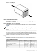
Bulk Power Supply Cooling
Cooling for the bulk power supplies is provided by two 60 mm fans contained within each BPS.
Air flows into the front of the BPS and is exhausted out of the top of the power supply through
upward facing vents near the rear of the supply. The air is then ducted out of the rear of the
chassis with minimal leakage into the cell airflow plenum.
Environmental Specifications 177