
HP Integrity rx7620 Server - User Service Guide, Sixth Edition

NOTE: Regardless of the grounding connection method used, the raised floor should be
grounded as an absolute safety minimum.
HP recommends the following approaches:
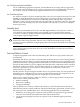
Excellent Add a signal reference grid to the subfloor. The grid should be made of aluminum
strips mounted to the subfloor. The strips should be 0.032 in. (0.08 cm) thick and
a minimum of 3.0 in. (8.0 cm) wide.
Connect each pedestal to four strips using 0.25 in. (6.0 mm) bolts tightened to the
manufacturer’s torque recommendation.
Better A grounded #6 AWG minimum copper wire grid mechanically clamped to floor
pedestals and properly bonded to the building/site ground.
Good Use the raised floor structure as a signal reference grid. In this case, the floor
must be designed as a ground grid with bolted stringers and corrosion resistive
plating (to provide low resistance and attachment points for connection to service
entrance ground and server equipment). The use of conductive floor tiles with
this style of grid further enhances ground performance. The structure needs to
be mechanically bonded to a known good ground point.
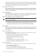
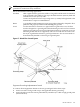
Figure C-1 Raised Floor Ground System
Equipment Grounding Implementation Details
To connect all HP equipment cabinets to the site ground grid. follow these steps:
1. Attach one end of each ground strap to the applicable cabinet ground lug.
2. Attach the other end to the nearest pedestal base (raised floor) or cable trough ground point
(nonraised floor).
Electrical Factors 185