
HP Integrity rx7620 Server - User Service Guide, Sixth Edition
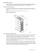
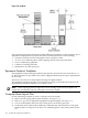
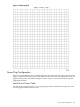
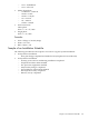


Figure C-3 Footprint
Space planning should also include the possible addition of equipment or other changes in space
requirements. Equipment layout plans should also include provisions for the following:
• Channels or fixtures used for routing data cables and power cables
• Access to air conditioning ducts, filters, lighting, and electrical power hardware
• Power conditioning equipment
• Cabinets for cleaning materials
• Maintenance area and spare parts
Equipment Footprint Templates
The equipment footprint template and floor plan grid are drawn to the same scale (0.25 in. = 1
ft). These templates are provided to show basic equipment dimensions and space requirements
for servicing.
The service areas shown on the template drawings are lightly shaded.
The equipment templates should be used with the floor plan grid to define the location of the
equipment that will be installed in your computer room.
NOTE: Photocopying typically changes the scale of drawings copied. If any templates are
copied, then all templates and floor plan grids must also be copied.
Computer Room Layout Plan
Use the following procedure to create a computer room layout plan:
1. Remove the floor plan grid from the document. See Figure C-4.
2. Remove a copy of each applicable equipment footprint template. See Figure C-3.
3. Cut out each template selected in step 2, then place it on the floor plan grid.
4. Position the pieces until the desired layout is obtained, then fasten the pieces to the grid.
Mark locations of computer room doors, air conditioning floor vents, utility outlets, and so
on.
194 General Site Preparation Guidelines