
HP Integrity rx7620 Server - User Service Guide, Sixth Edition


Cell Board
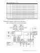
The cell board contains several hardware blocks connected by several data buses. The major
hardware blocks are the Central Processor Units (CPUs), the Cache Coherency Controller (CC),
the memory controllers, and the memory. Minor hardware blocks include Clock Distribution,
Power Distribution, Reset Circuit, and PDH Riser Board Interface. The buses include two Front
Side Buses (FBS0 and FBS1), a Memory (MID) bus, a Crossbar (XB) bus, and an I/O bus. All these
blocks come together at the CC chip.
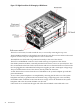
Figure 1-6 Cell Board
The HP Integrity rx7620 Server has a 48V distributed power system and receives the 48V power
from the system backplane board. The cell board contains DC-to-DC converters to generate the
required voltage rails. The DC-to-DC converters on the cell board do not provide N+1 redundancy.
Because of space limitations on the cell board, the PDH/PDHC circuitry resides on a riser board
that plugs into the cell board at a right angle. The cell board also includes clock circuits, test
circuits, and de-coupling capacitors.
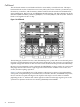
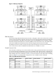
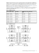
Figure 1-7 shows a simplified view of the memory subsystem. It consists of two independent
access paths, each path having its own address bus, control bus, data bus, and DIMMs . In practice,
the CC runs the two paths 180 degrees out of phase with respect to each other to facilitate
pipelining in the CC. Address and control signals are fanned out through register ports to the
synchronous dynamic random access memory (SDRAM) on the DIMMs.
22 Introduction