
HP Integrity rx7620 Server - User Service Guide, Sixth Edition
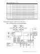


MP/SCSI Core I/O Board
The HP Integrity rx7620 Server accommodates two sets of MP/SCSI core I/O functionality. Each
MP/SCSI core I/O board set consists of a MP/SCSI board and a Procurium LAN/SCSI board. At
least one MP/SCSI board is required (independent of partitions). An additional MP/SCSI board
can be added as well (and is required in a dual partition system). Both MP/SCSI core I/O boards
are oriented vertically and plug into the system backplane. The MP/SCSI core I/O board
incorporates a dual channel Ultra160 SCSI controller and is hot-pluggable.
Procurium LAN/SCSI Board
At least one Procurium LAN/SCSI board is required for the minimum system configuration; two
are required in a dual partition system. The Procurium board is a standard PCI form factor card
with PCI card edge connectors. The PCI-X backplane has one slot location reserved for the
required Procurium board and another that can accommodate either a Procurium board or any
other supported add-in PCI-X card. The Procurium board is hot-pluggable.
Mass Storage (Disk) Backplane
Internal mass storage connections to disks are routed on the mass storage backplane, having
connectors and termination circuitry. All disks are hot-pluggable. The HP Integrity rx7620 Server
accommodates one internal removable media device. Therefore, only one power connector for
a removable media device is required on the mass storage backplane. The mass storage backplane
incorporates a circuit that allows power to the internal removable media device to be
programmatically cycled.
Server Description
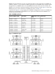
Dimensions
The dimensions of the HP Integrity rx7620 Server are as follows:
• Width: 44.45 cm (17.5 inches), constrained by EIA standard 19-inch racks.
• Depth: Defined by cable management constraints to fit into standard 36-inch deep racks
(Rittal/Compaq, Rosebowl I):
25.5 inches from front rack column to PCI connector surface.
26.7 inches from front rack column to MP core I/O connector surface.
30 inches overall package dimension, including 2.7 inches protruding in front of the front
rack columns.
• Height: 10U – 0.54 cm = 43.91 cm (17.287 inches). This is the appropriate height for a product
that consumes 10U of rack height while allowing adequate clearance between products
directly above and below this product. Fitting four server units per 2 m rack and upgrade
of current 10U height products in the future are the main height constraints.
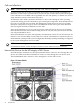
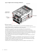
System Chassis
The mass storage section located in the front allows access to the 3.5-inch hard drives without
removal of the bezel. This is especially helpful when the system is mounted in the lowest position
in a rack. The mass storage bay also accommodates one 5.25-inch removable media device. The
front bezel must be removed to gain access to this device. The front panel display board, containing
LEDs and the system power switch, is located directly above the 5.25-inch removable media bay.
Below the mass storage section and behind a removable bezel are two PCI DC-to-DC power
converters.
The bulk power supply section is partitioned by a sealed metallic enclosure located in the bottom
of the package. This enclosure houses the N+1 fully redundant BPSs.
Server Description 27