
HP Integrity rx7620 Server - User Service Guide, Sixth Edition

3 Installing Additional Components
This chapter describes the installation of those components not installed at time of delivery.
Wheel Kit Installation
Before beginning the installation, compare the packing list with the contents of the wheel kit.
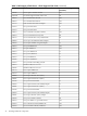
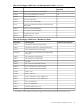
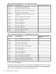
Table 3-1 Wheel Kit Packing List
QuantityDescriptionPart Number
1Wheel Kit consisting of the following components:A6753-04013
1Side coverA6753-04002
1Side coverA6753-04003
1Top coverA6753-04004
2Caster coverA6753-00007
1Right front caster assemblyA6753-04001
1Right rear caster assemblyA6753-04005
1Left front caster assemblyA6753-04006
1Left rear caster assemblyA6753-04007
4M4 x 0.7 8mm T15 steel zinc machine screw (Used to attach
each caster to the chassis)
0515-2478
1Plywood unloading rampA6093-44013
2Phillips head wood screw (Used to attach the ramp to the
pallet)
Not Applicable
Tools Required for Installation
The following list provides the installer with the recommended tools to perform the wheel kit
installation.
• Diagonal side cutters
• Safety glasses
• Torx screwdriver with T-15 bit
• Phillips head screwdriver
WARNING! Wear protective glasses while cutting the plastic bands around the shipping
container. These bands are under tension. When cut, they can spring back and cause serious eye
injury.
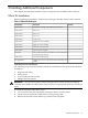
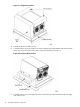
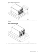
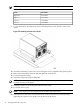
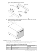
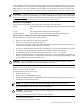
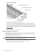
To install the wheel kit, follow these steps:
1. Cut and remove the polystrap bands securing the HP server to the pallet.
2. Lift the carton top from the cardboard tray resting on the pallet.
3. Remove the bezel kit carton and the top cushions from the pallet.
Wheel Kit Installation 41