
HP Integrity rx7620 Server - User Service Guide, Sixth Edition

NOTE: The caster part number is stamped on the caster mounting plate.
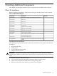
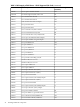
Table 3-2 Caster Part Numbers
Part NumberCaster
A6753-04001Right front
A6753-04005Right rear
A6753-04006Left front
A6753-04007Left rear
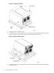
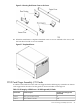
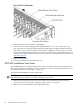
9. Locate and remove one of the four screws from the plastic pouch. Attach a caster to the
server.
Figure 3-5 Attaching a Caster to the Server
10. Attach the remaining casters to the server using the screws supplied in the plastic pouch.
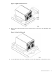
11. Remove the foam blocks from the left and right side of the server.
12. Locate the plywood ramp.
13. Attach the ramp to the edge of the pallet.
NOTE: There are two pre-drilled holes in the ramp. Use the two screws taped to the ramp
to attach the ramp to the pallet.
14. Carefully roll the server off the pallet and down the ramp.
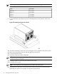
15. Locate the caster covers.
NOTE: The caster covers are designed to fit on either side of the server.
16. Insert the slot on the caster cover into the front caster. Secure the cover to the server by
tightening the captive screw on the cover at the rear of the server.
44 Installing Additional Components