
HP Integrity rx7620 Server - User Service Guide, Sixth Edition


• DB25 connector, by way of the M cable.
This RS-232 connector provides connections for a local console, external modem, and a UPS.
The server end of the M cable terminates in a DB25 connector. The opposite side of the cable
terminates in three DB9 connectors labeled CONSOLE, UPS, and REMOTE.
• 10/100 Base-T LAN RJ45 connector (for LAN and web console access).
This LAN uses standby power and is active when AC is present and the front panel power
switch is off.
• Internal LVD Ultra 160 SCSI channel for connections to internal mass storage.
• Internal SE Ultra SCSI channel for connection to an internal removable media device.
LAN/SCSI Connections
The LAN/SCSI board is a PCI form factor card that provides the basic external I/O connectivity
for the system.
Connections to the LAN/SCSI board include the following:
• PCI-X to PCI-X bridge for multi-device compatibility
• Internal LVD Ultra 160 SCSI channel for connections to internal mass storage
• External LVD Ultra 160 SCSI channel connected to a 68-pin VHDCI connector
• 10/100/1000 Base-T LAN RJ45 connector.
The primary LAN interface is located on the LAN/SCSI board installed in the rightmost slot
when viewing the system from the back.
Management Processor Access
NOTE: To access the MP for the initial installation, the M cable must first be connected to the
DB25 connector located on the primary MP/SCSI board. The primary MP/SCSI board is located
in the lower MP/SCSI board slot.
Setting Up the Customer Engineer Tool (PC)
The Customer Engineer (CE) Tool is usually a laptop. It enables communication with the MP in
the HP Integrity rx7620 Server. The MP monitors the activity of either a one partition or a
multiple-partition configuration.
During installation, communicating with the MP enables such tasks as:
• Verifying that the components are present and installed correctly
• Setting LAN IP addresses
• Shutting down cell board power
Communication with the MP is established by connecting the CE Tool to the local RS-232 port
on the MP core I/O card.
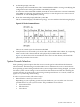
Setting CE Tool Parameters
• 8/none (parity)
• 9600 baud
• na (Receive)
• na (Transmit)
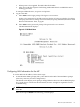
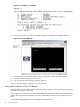
After powering on the CE Tool, ensure the communications settings are as follows:
If the CE Tool is a laptop using Reflection, ensure communications settings are in place.
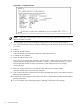
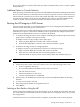
To ensure communications settings are in place, follow these steps:
MP Core I/O Connections 61