
HP Integrity rx7620 Server - User Service Guide, Sixth Edition
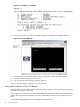


1. From the Reflection main screen, select Connection and select Connection Setup.
2. Select Serial Port.
3. Select Com1.
4. Check the settings and change, if required.
Go to More Settings to set Xon/Xoff. Click OK to close the More Settings window.
5. Click OK to close the Connection Setup window.
6. Pull down the Setup menu and select Terminal (under the Emulation tab).
7. Select any terminal type.
8. Click Apply.
This option is not highlighted if the terminal type you want is already selected.
9. Click OK.
Connecting the CE Tool to the Local RS-232 Port On the MP
This connection enables direct communications with the MP. Only one window can be created
on the CE Tool to monitor the MP. When enabled, it provides direct access to the MP and any
partition.
To connect the CE Tool to the local RS-232 port on the MP, follow these steps:
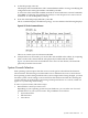
1. Connect one end of a null modem cable (9-pin to 9-pin) (Part Number 5182-4794) to the M
cable connector labeled CONSOLE.
2. Connect the other end of the RS-232 cable to the CE Tool.
Standby Power and Logging In to the MP
After connecting the serial device, it is possible to log in to the MP. Housekeeping power (also
known as standby power) is generated as soon as AC power is applied to the server. Because
the MP uses standby power, it is possible to log in to the MP even when the power switch is in
the OFF position. The power switch is a DC power switch that controls +48V DC.
Before powering on the HP Integrity rx7620 Server for the first time, follow these steps:
1. Verify that the AC voltage at the input source is within specifications for each server being
installed.
2. If not already done so, power on the serial display device.
The preferred tool is the CE tool running Reflection.
To power on the MP, set up a communications link and log in to the MP, follow these steps:
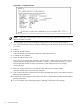
1. Connect the server to AC power.
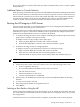
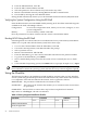
On the front of the HP Integrity rx7620 Server, a solid green Standby Power LED, a solid
green MP Present LED, and a flashing amber Attention LED illuminates after about 30
seconds.
Figure 4-7 Front Panel Display
2. Check the bulk power supply LED for each BPS.
When on, the breakers distribute power to the BPSs. AC power is present at the BPSs:
62 Cable Connections