HP Integrity rx7640 and HP 9000 rp7440 Servers Installation Guide HP Part Number: AB312-9012B Published: November 2011 Edition: 5
© Copyright 2006, 2011 Hewlett-Packard Development Company, L.P Legal Notices The information contained herein is subject to change without notice. The only warranties for HP products and services are set forth in the express warranty statements accompanying such products and services. Nothing herein should be construed as constituting an additional warranty. HP shall not be liable for technical or editorial errors or omissions contained herein. Microsoft and Windows are U.S.
Contents About this Document......................................................................................5 Book Layout.............................................................................................................................5 Intended Audience....................................................................................................................5 Publishing History.........................................................................................................
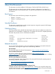
Reference URL...............................................................................................................46 Cabling and Power Up............................................................................................................46 Checking the Voltage.........................................................................................................46 Preface.......................................................................................................................
About this Document This document covers the installation of HP Integrity rx7640 and HP 9000 rp7440 Servers. This document does not describe system software or partition configuration in any detail. For detailed information concerning those topics, See the HP System Partitions Guide: Administration for nPartitions.
Web Site for HP Technical Support: HP Support Center is located at the following website: http://www.hp.com/go/hpsc It provides comprehensive support information for IT professionals on a wide variety of topics, including software, hardware, and networking. Typographic Conventions The following notational conventions are used in this publication. WARNING! A warning lists requirements that you must meet to avoid personal injury.
For HP technical support: • In the United States, for contact options see the Contact HP United States webpage: (http:// welcome.hp.com/country/us/en/contact_us.html) To contact HP by phone: • ◦ Call 1-800-HP-INVENT (1-800-474-6836). This service is available 24 hours a day, 7 days a week. For continuous quality improvement, calls may be recorded or monitored. ◦ If you have purchased a Care Pack (service upgrade), call 1-800-633-3600.
1 HP Integrity rx7640 Server and HP 9000 rp7440 Server Overview The HP Integrity rx7640 and HP 9000 rp7440 Servers are members of HP’s business-critical computing platform family in the mid-range product line. The information in chapters one through six of this guide applies to the HP Integrity rx7640 and HP 9000 rp7440 Servers, except for a few items specifically denoted as applying only to the HP Integrity rx7640 Server. Chapter seven covers any information specific to the HP 9000 rp7440 Server only.
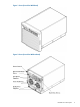
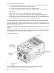
Figure 1 Server (Front View With Bezel) Figure 2 Server (Front View Without Bezel) Detailed Server Description 9
The server has the following dimensions: • Depth: Defined by cable management constraints to fit into standard 36-inch deep rack: 25.5 inches from front rack column to PCI connector surface 26.7 inches from front rack column to MP Core I/O connector surface 30 inches overall package dimension, including 2.7 inches protruding in front of the front rack columns. • Width: 44.45 cm (17.5 inches), constrained by EIA standard 19 inch racks. • Height: 10U – 0.54 cm = 43.91 cm (17.287 inches).
The PCI OLR fan modules are located in front of the PCI-X cards. These six 9.2-cm fans are housed in plastic carriers. They are configured in two rows of three fans. Four OLR system fan modules, externally attached to the chassis, are 15-cm (6.5-inch) fans. Two fans are mounted on the front surface of the chassis and two are mounted on the rear surface. The cell boards are accessed from the right side of the chassis behind a removable side cover.
• Management processor (MP) status LED (tri-color) • Cell 0, 1 status (tri-color) LEDs Figure 5 Front Panel LEDs and Power Switch Cell Board The cell board, illustrated in Figure 6, contains the processors, main memory, and the CC application specific integrated circuit (ASIC) which interfaces the processors and memory with the I/O, and to the other cell board in the server. The CC is the heart of the cell board, enabling communication with the other cell board in the system.
• Incoming and outgoing crossbar bus that goes off board to the other cell board • PDH bus that goes to the PDH and microcontroller circuitry All of these buses come together at the CC chip. Because of space limitations on the cell board, the PDH and microcontroller circuitry resides on a riser board that plugs into the cell board at a right angle. The cell board also includes clock circuits, test circuits, and de-coupling capacitors.
Figure 7 CPU Locations on Cell Board Memory Subsystem Figure 8 shows a simplified view of the memory subsystem. It consists of two independent access paths, each path having its own address bus, control bus, data bus, and DIMMs . Address and control signals are fanned out through register ports to the synchronous dynamic random access memory (SDRAM) on the DIMMs. The memory subsystem comprises four independent quadrants.
Figure 8 Memory Subsystem DIMMs The memory DIMMs used by the server are custom designed by HP. Each DIMM contains DDR-II SDRAM memory that operates at 533 MT/s. Industry standard DIMM modules do not support the high availability and shared memory features of the server. Therefore, industry standard DIMM modules are not supported. The server supports DIMMs with densities of 1, 2, 4, and 8 GB.
On the server, each nPartition has its own dedicated portion of the server hardware which can run a single instance of the operating system. Each nPartition can boot, reboot, and operate independently of any other nPartitions and hardware within the same server complex. The server complex includes all hardware within an nPartition server: all cabinets, cells, I/O chassis, I/O devices and racks, management and interconnecting hardware, power supplies, and fans.
• DC-to-DC converters • Power monitor logic • Two local bus adapter (LBA) chips that create internal PCI buses for communicating with the core I/O card The backplane also contains connectors for attaching the cell boards, the PCI-X backplane, the core I/O board set, SCSI cables, bulk power, chassis fans, the front panel display, intrusion switches, and the system scan card. Unlike Superdome or the HP Integrity rx8640, there are no Crossbar Chips (XBC) on the system backplane.
rope links for a total aggregate bandwidth of approximately 11.5 GB/sec. Each LBA acts as a bus bridge, supporting either one or two ropes and capable of driving 33 MHz or 66 MHz for PCI cards. The LBAs can also drive at 66 MHz or 133 MHz for PCI-X cards, and at 266 MHz for PCI-X mode 2 cards installed in mode 2 capable slots. Figure 11 PCI-X Board to Cell Board Block Diagram Table 3 and Table 4 list the mapping of PCI-X slots to boot paths.
Table 4 PCI-X Paths Cell 1 (continued) Cell PCI-X Slot I/O Chassis Path 1 4 1 1/0/14/1 1 5 1 1/0/6/1 1 6 1 1/0/4/1 1 7 1 1/0/2/1 1 8 1 1/0/1/1 The server supports two internal SBAs. Each SBA provides the control and interfaces for eight PCI-X slots. The interface is through the rope bus (16 ropes per SBA). For each SBA, the ropes are divided in the following manner: • A single rope is routed to support the core I/O boards through LBAs located on the system backplane.
Table 5 PCI-X Slot Types (continued) I/O Partition Slot1 1 1 Maximum MHz Maximum Peak Ropes Bandwidth Supported Cards PCI Mode Supported 3 266 2.13 GB/s 012/013 3.3 V or 1.5 V PCI-X Mode 2 2 133 1.06 GB/s 010/011 3.3 V PCI or PCI-X Mode 1 1 133 1.06 GB/s 008/009 3.3 V PCI or PCI-X Mode 1 8 133 533 MB/s 001 3.3 V PCI or PCI-X Mode 1 7 133 1.06 GB/s 002/003 3.3 V PCI or PCI-X Mode 1 6 266 2.13 GB/s 004/005 3.3 V or 1.5 V PCI-X Mode 2 5 266 2.13 GB/s 006/007 3.
The ropes in each I/O partition are distributed as follows: • One PCI-X ASIC is connected to each I/O chip with a single rope capable of peak data rates of 533Mb/s (PCIX-66). • Three PCI-X ASICs are connected to each I/O chip with dual ropes capable of peak data rates of 1.06Gb/s (PCIX-133). • Four PCIe ASICs are connected to each I/O chip with dual fat ropes capable of peak data rates of 2.12Gb/s (PCIe x8). In addition, each I/O chip provides an external single rope connection for the core I/O.
Table 6 PCI-X/PCIe Slot Types (continued) I/O Partition Slot1 Maximum Peak Maximum MHz Bandwidth Ropes Supported Cards PCI Mode Supported 2 133 1.06 GB/s 010/011 3.3 V PCI or PCI-X Mode 1 1 133 1.06 GB/s 008/009 3.3 V PCI or PCI-X Mode 1 1. Each slot will auto select the proper speed for the card installed up to the maximum speed for the slot. Placing high speed cards into slow speed slots will cause the card to be driven at the slow speed. 2.
2 Installing the Server Inspect shipping containers when the equipment arrives at the site. Check equipment after the packing has been removed. This chapter discusses how to inspect and install the server. Receiving and Inspecting the Server Cabinet This section contains information about receiving, unpacking and inspecting the server cabinet. NOTE: The server will ship in one of three different configurations.
Figure 12 Removing the Polystraps and Cardboard 3. 4. Remove the corrugated wrap from the pallet. Remove the packing materials. CAUTION: Cut the plastic wrapping material off rather than pull it off. Pulling the plastic covering off represents an electrostatic discharge (ESD) hazard to the hardware. 5. Remove the four bolts holding down the ramps, and remove the ramps.
Figure 13 Removing the Shipping Bolts and Plastic Cover Receiving and Inspecting the Server Cabinet 25
6. Remove the six bolts from the base that attaches the rack to the pallet. Figure 14 Preparing to Roll Off the Pallet WARNING! Be sure that the leveling feet on the rack are raised before you roll the rack down the ramp, and any time you roll the rack on the casters. Use caution when rolling the cabinet off the ramp. A single server in the cabinet may weigh in excess of 280 lbs. It is strongly recommended that two people roll the cabinet off the pallet.
Figure 15 Securing the Cabinet Standalone and To-Be-Racked Systems Servers shipped in a stand-alone or to-be-racked configuration must have the core I/O handles and the PCI towel bars attached at system installation. Obtain and install the core I/O handles and PCI towel bars from the accessory kit A6093-04046. The towel bars and handles are the same part. See the following service note A6093A-11. Rack-Mount System Installation Information is available to help with rack-mounting the server.
3. Remove the systems left and right side covers. NOTE: The latest lift handles available for the 2-cell servers are symmetrical and can be installed on either side of the server. 4. 5. Locate one handle and ensure the two thumbscrews are removed from its front flange. Insert the 2 protruding tabs on rear flange of handle into the slotted keyways in the server’s chassis. See Figure 16. Figure 16 Inserting Rear Handle Tabs into Chassis 6.
Figure 17 Attaching the Front of Handle to Chassis 7. 8. 9. 10. 11. 12. Repeat steps 2—4 to install the other handle on the other side of the server. After handles are secured, server is ready to lift. Handles are removed in reverse order of steps 2—4. After moving the server, remove the lift handles from the chassis. After the server is secured, replace the previously removed cell boards and bulk power supplies. Reinstall the side covers and front bezel.
Figure 18 RonI Lifter 1. 2. 3. 30 Obtain the HP J1530C Rack Integration Kit Installation Guide before proceeding with the rack mount procedure. This guide covers these important steps: • Installing the anti-tip stabilizer kit (A5540A) • Installing the ballast kit (J1479A) • Installing the barrel nuts on the front and rear columns • Installing the slides Follow the instructions on the outside of the server packaging to remove the banding and carton top from the server pallet.
Figure 19 Positioning the Lifter to the Pallet 4. 5. Carefully slide server onto lifter forks. Slowly raise the server off the pallet until it clears the pallet cushions. Figure 20 Raising the Server Off the Pallet Cushions 6. Carefully roll the lifter and server away from the pallet. Do not raise the server any higher than necessary when moving it over to the rack.
7. Follow the HP J1530C Rack Integration Kit Installation Guide to complete these steps: • Mounting the server to the slides • Installing the cable management arm (CMA) • Installing the interlock device assembly (if two servers are in the same cabinet) Wheel Kit Installation Compare the packing list (Table 7) with the contents of the wheel kit before beginning the installation. For a more updated list of part numbers, go to the HP Part Surfer web site at the following website: http://www.partsurfer.
Figure 21 Component Locations 4. 5. Unfold bottom cardboard tray. Carefully tilt the server and place one of the foam blocks (A6093-44002) under the left side of the server. Do not remove any other cushions until instructed to do so. Figure 22 Left Foam Block Position 6. Carefully tilt the server and place the other foam block provided in the kit under the right side of the server.
Figure 23 Right Foam Block Position 7. Remove the cushions from the lower front and rear of the server. Do not disturb the side cushions. Figure 24 Foam Block Removal 8. Locate and identify the caster assemblies. Use the following table to identify the casters. NOTE: 34 Installing the Server The caster part number is stamped on the caster mounting plate.
Table 8 Caster Part Numbers 9. Caster Part Number Right front A6753-04001 Right rear A6753-04005 Left front A6753-04006 Left rear A6753-04007 Locate and remove one of the four screws from the plastic pouch. Attach the a caster to the server. Figure 25 Attaching a Caster to the Server 10. 11. 12. 13. Attach the remaining casters to the server using the screws supplied in the plastic pouch. Remove the foam blocks from the left and right side of the server. Locate the plywood ramp.
Figure 26 Securing Each Caster Cover to the Server 17. Wheel kit installation is complete when both caster covers are attached to the server, and the front bezel and all covers are installed. Figure 27 Completed Server Installing the Power Distribution Unit The server may ship with a power distribution unit (PDU). Two 60 A PDUs available for the server. Each PDU 3 U high and is mounted horizontally between the rear columns of the server cabinet. The 60 A PDUs are delivered with an IEC-309 60 A plug.
The 60A IEC PDU has four 16A circuit breakers and is constructed for International use. Each of the four circuit breakers has two IEC-320 C19 outlets providing a total of eight IEC-320 C19 outlets. Each PDU is 3U high and is rack-mounted in the server cabinet. Documentation for installation will accompany the PDU. The documentation can also be found at the external Rack Solutions Web site at: http://www.hp.com/go/rackandpower This PDU might be referred to as a Relocatable Power Tap outside HP.
Figure 28 Disk Drive and DVD Drive Location Use the following procedure to install the disk drives: 1. Be sure the front locking latch is open, then position the disk drive in the chassis. 2. Slide the disk drive into the chassis, a slow firm pressure is needed to properly seat the connector. 3. Press the front locking latch to secure the disk drive in the chassis. 4.
Figure 29 Removable Media Location 1. 2. 3. 4. 5. Remove the front bezel. Remove the filler panel from the server. Install the left and right media rails and clips to the drive. Connect the cables to the rear of the drive Fold the cables out of the way and slide the drive into the chassis. The drive easily slides into the chassis; however, a slow firm pressure is needed for proper seating. The front locking tab will latch to secure the drive in the chassis. 6. 7. 8. Replace the front bezel.
Table 9 HP Integrity rx7640 PCI-X and PCIe I/O Cards (continued) Part Number Card Description A5506B 4-port 10/100b-TX A5838A 2-port Ultra2 SCSI/2-Port 100b-T Combo A6386A Hyperfabric II A6749A 64-port Terminal MUX A6795A 2G FC Tachlite B Next Gen 1000b-T b A6826A 2-port 2Gb FC B A6828A 1-port U160 SCSI B B A6829A 2-port U160 SCSI B B A6847A Next Gen 1000b-SX b b A6869B Obsidian 2 VGA/USB B A7011A 1000b-SX Dual Port b b b A7012A 1000b-T Dual Port b b b A7173A 2-po
Table 9 HP Integrity rx7640 PCI-X and PCIe I/O Cards (continued) Part Number Card Description HP-UX AD168A1 Emulex 4Gb/s DC AD193A 1 port 4Gb FC & 1 port GbE HBA PCI-X Bb B AD194A 2 port 4Gb FC & 2 port GbE HBA PCI-X Bb B AD278A 8-Port Terminal MUX AD279A 64-Port Terminal MUX AD307A LOA (USB/VGA/RMP) B B J3525A 2-port Serial 337972-B21 SA P600 (Redstone) Windows® Linux® B B B B VMS PCIe Cards A8002A Emulex 1–port 4Gb FC PCIe B B A8003A Emulex 2–port 4Gb FC PCIe B B AD
NOTE: The PCI I/O card installation process varies depending on what version of the HP-UX operating system you are running on your system. PCI I/O card installation procedures should be downloaded from the following website: http://www.hp.com/go/bizsupport. Select a following guide and enter the title in the search field for background information and procedures to add a new PCI I/O card using online addition: • nPartition Administrator's Guide • Interface Card OL* Support Guide for HP-UX 11.
Adding a PCI I/O Card Using the Attention Button The following prerequisites for this procedure: • Drivers for the card have already been installed. • No drivers are associated with the slot. • The green power LED is steady OFF. Should the empty slot be in the ON state use the olrad command or the pdweb tool to power the slot OFF. • The yellow attention LED if steady OFF or is blinking if a user has requested the slot location.
Figure 30 PCI I/O Slot Details 7. 8. Wait for the green power LED to stop blinking. Check for errors in the hotplugd daemon log file (default: /var/adm/hotplugd.log). The critical resource analysis (CRA) performed while doing an attention button initiated add action is very restrictive and the action will not complete–it will fail–to protect critical resources from being impacted. For finer control over CRA actions use pdweb or the olrad command.
Figure 31 PCI/PCI-X Card Location IMPORTANT: Some PCI I/O cards, such as the A6869B VGA/USB PCI card, cannot be added or replaced online (while Windows® remains running). For these cards, you must shut down Windows on the nPartition before performing the card replacement or addition. See the section on Shutting Down nPartitions and Powering off Hardware Components in the appropriate service guide. 1. 2. 3. 4. 5. 6. 7.
Reference URL There are many features available for HP Servers at this website including links to download Windows Drivers. HP Servers Technical Support http://www.hp.com/support/itaniumservers Cabling and Power Up After the system has been unpacked and moved into position, it must be connected to a source of AC power. The AC power must be checked for the proper voltage before the system is powered up. This chapter describes these activities.
1. 2. 3. Measure the voltage between L1 and L2. This is considered to be a phase-to-phase measurement in North America. In Europe and certain parts of Asia-Pacific, this measurement is referred to as a phase-to-neutral measurement. The expected voltage should be between 200–240 V AC regardless of the geographic region. Measure the voltage between L1 and ground. In North America, verify that this voltage is between 100–120 V AC.
Figure 33 Safety Ground Reference Check WARNING! SHOCK HAZARD Risk of shock hazard while testing primary power. Use properly insulated probes. Be sure to replace access cover when finished testing primary power. 1. Measure the voltage between A0 and A1 as follows: a. Take the AC voltage down to the lowest scale on the volt meter. b. Insert the probe into the ground pin for A0. c. Insert the other probe into the ground pin for A1. d. Verify that the measurement is between 0-5 V AC.
Figure 34 Safety Ground Reference Check WARNING! SHOCK HAZARD Risk of shock hazard while testing primary power. Use properly insulated probes. Be sure to replace access cover when finished testing primary power. 1. Measure the voltage between A0 and A1 as follows: a. Take the AC voltage down to the lowest scale on the volt meter. b. Insert the probe into the ground pin for A0. c. Insert the other probe into the ground pin for A1. d. Verify that the measurement is between 0-5 V AC.
4. Measure the voltage between A1 and B1 as follows: a. Take the AC voltage down to the lowest scale on the volt meter. b. Insert the probe into the ground pin for A1. c. Insert the other probe into the ground pin for B1. d. Verify that the measurement is between 0-5 V AC. If the measurement is 5 V or greater, escalate the situation. Do not attempt to plug the power cord into the server cabinet.
8. Set the site power circuit breaker to ON. 9. Set the server power to ON. 10. Check that the indicator light on each power supply is lit. Connecting AC Input Power The server can receive AC input power from two different AC power sources. If two separate power sources are available, the server can be plugged into the separate power sources, increasing system realibility if one power source fails. The main power source is defined to be A0 and B0. The redundant power source is defined to be A1 and B1.
The current power grid configuration is: Single grid Power grid configuration preference. 1. Single grid 2. Dual grid Select Option: Figure 37 Distribution of Input Power for Each Bulk Power Supply WARNING! Voltage is present at various locations within the server whenever a power source is connected. This voltage is present even when the main power switch is in the off position. To completely remove power, all power cords must be removed from the server.
Two Cell Server Installation (rp7410, rp7420, rp7440, rx7620, rx7640) There are 3 studs with thumb nuts located at the rear of the server chassis. The line cord anchor installs on these studs. To install the line cord anchor: 1. Remove and retain the thumb nuts from the studs. 2. Install the line cord anchor over the studs. See Figure 38: “Two Cell Line Cord Anchor (rp7410, rp7420, rp7440, rx7620, rx7640)”. 3. Tighten the thumb nuts onto the studs. 4. Weave the power cables through the line cord anchor.
MP/SCSI I/O Connections The MP/SCSI board is required to update firmware, access the console, turn partition power on or off, access one of the HDDs and one of the removable media devices, and utilize other features of the system. For systems running a single partition, one MP/SCSI board is required. A second MP/SCSI board is required for a dual-partition configuration, or if you want to enable primary or secondary MP failover for the server.
If the CE Tool is a laptop using Reflection 1, ensure communications settings are in place, using the following procedure: 1. From the Reflection 1 Main screen, pull down the Connection menu and select Connection Setup. 2. Select Serial Port. 3. Select Com1. 4. Check the settings and change, if required. Go to More Settings to set Xon/Xoff. Click OK to close the More Settings window. 5. 6. 7. 8. Click OK to close the Connection Setup window.
Figure 40 Front Panel Display 2. Check the bulk power supply LED for each BPS. When on, the breakers distribute power to the BPSs. AC power is present at the BPSs: • When power is first applied. The BPS LEDs will be flashing amber. • After 30 seconds has elapsed. The flashing amber BPS LED for each BPS becomes a flashing green LED. See power cord policies to interpret LED indicators. 3. Log in to the MP: a. Enter Admin at the login prompt. The login is case sensitive.
1. At the MP Main Menu prompt (MP>) enter cm to enter the MP Command. NOTE: If the Command Menu is not shown, enter q to return to the MP Main Menu, then enter cm.. 2. From the MP Command Menu prompt (MP:CM>) enter lc (for LAN configuration). The screen displays the default values and asks if you want to modify them. Write down the information or log it in a file, as it may be required for future troubleshooting. See Figure 42 (page 57).
10. A screen similar to the following is displayed, allowing verification of the settings: Figure 43 The ls Command Screen 11. To return to the MP main menu, enter ma. 12. To exit the MP, enter x at the MP main menu. Accessing the Management Processor via a Web Browser Web browser access is an embedded feature of the MP/SCSI card. The Web browser enables access to the server through the LAN port on the core I/O card. MP configuration must be done from an ASCII console connected to the Local RS232 port..
Figure 44 Example sa Command 5. 6. 7. Enter W to modify web access mode. Enter option 2 to enable web access. Launch a Web browser on the same subnet using the IP address for the MP LAN port. Figure 45 Browser Window 8. Select the emulation type you want to use. 9. Click anywhere on the Zoom In/Out title bar to generate a full screen MP window. 10. Login to the MP when the login window appears. Access to the MP via a Web browser is now possible.
After logging in to the MP, verify that the MP detects the presence of all the cells installed in the cabinet. It is important for the MP to detect the cell boards. If it does not, the partitions will not boot. To determine if the MP detects the cell boards: 1. At the MP prompt, enter cm. This displays the Command Menu. The Command Menu enables viewing or modifying the configuration and viewing the utilities controlled by the MP. To view a list of the commands available, enter he.
2. Select the appropriate console device (deselect unused devices): a. Choose the Boot option maintenance menu choice from the main Boot Manager Menu. b. Select the Console Output, Input or Error devices menu item for the device type you are modifying: c. • Select Active Console Output Devices • Select Active Console Input Devices • Select Active Console Error Devices Available devices will be displayed for each menu selection.
Additional Notes on Console Selection Each Operating System makes decisions based on the EFI Boot Maintenance Manager menu’s Select Active Console selections to determine where to send its output. If incorrect console devices are chosen the OS may fail to boot or will boot with output directed to the wrong location. Therefore, any time new potential console devices are added to the system or anytime NVRAM on the system is cleared console selections should be reviewed to ensure that they are correct.
4. 5. Enter the partition number of the partition to boot. Press Enter. Selecting a Boot Partition Using the MP At this point in the installation process, the hardware is set up, the MP is connected to the LAN, the AC and DC power have been turned on, and the self-test is completed. Now the configuration can be verified. After the DC power on and the self-test is complete, use the MP to select a boot partition. 1. From the MP Main Menu, enter cm. 2. From the MP Command Menu, enter bo. 3.
CPUs reside in the purchased system and are tracked as HP-owned assets. A nominal “Right-To-Access Fee” is paid to HP for each Instant Capacity CPU in the system. Any number of Instant Capacity CPUs can be activated at any time. Activating an Instant Capacity CPU automatically and promptly transforms the Instant Capacity CPU into an instantly ordered and fulfilled CPU upgrade that requires payment.
Table 11 Factory-Integrated Installation Checklist (continued) Procedure In-process Completed Remove corrugated wrap from the pallet Remove four bolts holding down the ramps and remove the ramps Remove antistatic bag Check for damage (exterior and interior) Position ramps Roll cabinet off ramp Unpack the peripheral cabinet (if ordered) Unpack other equipment Remove and dispose of packaging material Move cabinet(s) and equipment to computer room Move cabinets into final position Position cabinets next to
Table 11 Factory-Integrated Installation Checklist (continued) Procedure Configure remote login (if required). See Appendix B.
Index A ASIC, 8 B backplane mass storage, 22 PCI, 17, 22 system, 11, 17, 22 BPS (Bulk Power Supply), 56 C cell board, 10, 11, 12, 54, 59, 62 verifying presence, 59 cell controller, 8 checklist installation, 64 cm (Command Menu) command, 60 co (Console) command, 62 command co (Console), 62 CTRL-B, 62 di (Display), 63 vfp (Virtual Front Panel), 62 commands cm (Command Menu), 60 du (display MP bus topology), 60 controls, 11 core I/O, 8 D DAT, 8 di (Display) command, 63 DIMMs, 14 memory, 14 disk internal, 22
R Reflection 1, 55, 62 rootcell setting value of, 62 S serial display device connecting, 54, 55 recommended windows, 62 setting parameters, 54 server front panel, 11 service processor, 8 Standby power LED, 11 status LEDs, 11 system backplane, 11, 17, 22 system configuration, verifying, 63 T turbocoolers, 8 V verifying system configuration, 63 W warranty, 23 68 Index