
HP Integrity rx7640 and HP 9000 rp7440 Servers User Service Guide


a. Check the LED for each bulk power supply (BPS).
The LED is located in the lower left hand corner of the power supply face. Table 22 shows the
states of the LEDs.
b. Verify that the power supply and a minimum of two power cords are plugged in to the chassis.
A yellow LED indicates that the line cord connections are not consistent with the pwrgrd
settings.
NOTE: A minimum of two power cords must be connected to A0 and B0 or A1 and B1. If
the front panel yellow power LED continues to flash with two power cords connected then the
server may not be in an N+1 configuration. Four power cords will be required.
c. Remove and replace any suspect BPS.
The Server Powers On But Fails Power-On Self Test
Use this checklist when the server fails power on self test (POST):
a. Check for error messages on the system console.
b. Check for fault LEDs.
c. Check for error messages in the MP logs.
Server LED Indicators
The server has LEDs that indicate the health of the server. This section defines those LEDs.
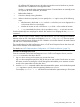
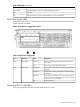
Front Panel LEDs
There are five LEDs located on the front panel.
Figure 47 Front Panel with LED Indicators
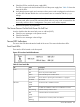
Table 21 Front Panel LEDs
DescriptionStatusLED
48 V OffOffPower
BPS or PCI power module absent.Red
Non-redundant power condition existsYellow
Server cabinet is powering off. OS shutdown is in progress.Flash Green
48 V Good.On Green
At least one MP is installed and activeGreenMP Status
(solid)
No MPs are installed or at least one is installed but not activeOff
Cabinet overtemp condition existsRed (flashing)
Cabinet shutdown for thermal reasonsRed
(solid)
Cabinet fan slow or failed, master slave failover.Yellow
(flashing)
Server LED Indicators 107