
HP Integrity rx7640 and HP 9000 rp7440 Servers User Service Guide


Server Management Behavior
This section describes how the system responds to over-temperature situations, how the firmware
controls and monitors fans, and how it controls power to the server.
Thermal Monitoring
The manageability firmware is responsible for monitoring the ambient temperature in the server
and taking appropriate action if this temperature becomes too high. The ambient temperature of
the server is broken into four ranges: normal, overtemp low (OTL), overtemp medium (OTM), and
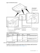
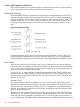
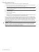
overtemp high (OTH). Figure 56 shows the actions taken at each range transition. Actions for
increasing temperatures are shown on the left; actions for decreasing temps are shown on the
right.
Figure 56 Temperature States
On large temperature swings, the server will transition through all states in order. It might go to
the following state immediately, but each of the preceding actions will occur. If the temperature
reaches the highest range, the server will be shut down immediately by the manageability firmware.
Fan Control
There are three sets of fans in the system: those on the I/O bay, the front and rear fans that are
connected to the main backplane, and those on the cell boards. The front fans are run off of standby
power, and will be running any time AC input power is supplied to the server. All of the fans turn
on when 48 V power is supplied to the system.
As shown Figure 56, the fan behavior is related to the temperature state. The fans will be set to
high speed when the ambient temperature is anywhere above the normal operating range. The
front and rear fans will be set to high speed any time a chassis intrusion switch is triggered when
removing a side cover.
Altimeter Circuit
The system backplane contains an altimeter circuit. This circuit is used to adjust the chassis fan
speeds for the operating altitude at power on and during MP initialization. The chassis fans consist
of the two front fans, two rear fans, and the six PCI-X I/O assembly fans. If an altimeter failure is
detected, the information is logged as an Event ID then propagated to the OS level to be picked
up by monitoring diagnostics.
The altimeter circuit is checked at power on by the MP. If an expected value is returned from the
altimeter circuit, the altimeter is determined good. The altimeter reading is then set in non-volatile
random access memory (NVRAM) on board the core I/O card. If the value is ever lost like for a
core I/O replacement, the NVRAM will be updated at next boot provided the altimeter is functioning
118 Server Troubleshooting