
HP Integrity rx7640 and HP 9000 rp7440 Servers User Service Guide


See Chapter 4 “Operating System Boot and Shutdown” for details on determining the nPartition
boot state and shutting down HP-UX.
3. Access the MP Command menu.
From the MP Main menu, enter CM to access the Command Menu.
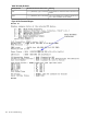
4. Use the MP Command Menu PS command to check details about the hardware component
you plan to power off.
The PS command enables you to check the status of the cabinet, system backplane, MP core
I/O, PCI power domains—or bricks—in the I/O card cage and cells.
5. Use the MP Command Menu PEcommand to power off the hardware component.
Using the PE command, you can power on or off the cabinet (including all cells and I/O in
the cabinet), individual cells along with their associated I/O domain, or PCI power domains
(bricks).
Using the Command menu PE command to manage cabinet power is equivalent to using the
front panel power switch.
6. To disable all power in the entire cabinet, disconnect all power cords to disable all
housekeeping power.
IMPORTANT: Because of power redundancy capabilities, it is important to plug each power
cord into its proper receptacle. Label each power cord to indicate its correct receptacle.
WARNING! Ensure that the cabinet power has been turned off before disconnecting any
power cords.
7. Perform the hardware removal and replacement procedure for the powered off component.
Powering On the System
To power on the system after a repair:
1. If needed, reconnect all power cords to the appropriate receptacles and power on the system.
2. Use the MP Command Menu PE command to power on the hardware component that was
powered off and replaced.
3. Use the PS command to verify that power is enabled to the newly replaced part. For example:
Enter Cfrom within the PS command to select cell.
If power is absent from the part, enter the PE command and select Tto power on the entire
cabinet.
NOTE: You may need to allow time for some components to complete power on self test
(POST) before a complete status is available.
4. Reboot each nPartition. See Chapter 4 “Operating System Boot and Shutdown.”
5. Verify system functionality by using the Online Diagnostic Support Tools Manager (STM)
exerciser.
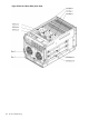
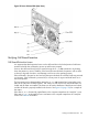
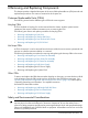
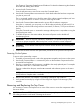
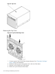
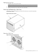
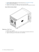
Removing and Replacing the Top Cover
It is necessary to remove and replace one or more of the covers to access the components within
the server chassis.
CAUTION: Observe all ESD safety precautions before attempting this procedure. Failure to follow
ESD safety precautions could result in damage to the server.
Removing and Replacing the Top Cover 127