
HP Integrity rx7640 and HP 9000 rp7440 Servers User Service Guide
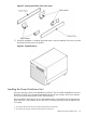

7. Follow the HP J1530C Rack Integration Kit Installation Guide to complete these steps:
• Mounting the server to the slides
• Installing the cable management arm (CMA)
• Installing the interlock device assembly (if two servers are in the same cabinet)
Wheel Kit Installation
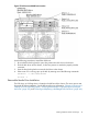
Compare the packing list (Table 16) with the contents of the wheel kit before beginning the
installation. For a more updated list of part numbers, go to the HP Part Surfer web site at the
following website:
http://www.partsurfer.hp.com
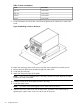
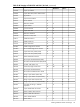
Table 16 Wheel Kit Packing List
QuantityDescriptionPart Number
1Wheel Kit consisting of the following components:A6753-04013
1Side coverA6753-04002
1Side coverA6753-04003
1Top coverA6753-04004
2Caster coverA6753-00007
1Right front caster assemblyA6753-04001
1Right rear caster assemblyA6753-04005
1Left front caster assemblyA6753-04006
1Left rear caster assemblyA6753-04007
4M4 x 0.7 8mm T15 steel zinc machine screw (Used to attach
each caster to the chassis)
0515-2478
1Plywood unloading rampA6093-44013
2Phillips head wood screw (Used to attach the ramp to the
pallet)
Not Applicable
Tools Required for Installation
The following list provides the installer with the recommended tools to perform the wheel kit
installation.
• Diagonal side cutters
• Safety glasses
• Torx screwdriver with T-15 bit
• Phillips head screwdriver
WARNING! Wear protective glasses while cutting the plastic bands around the shipping container.
These bands are under tension. When cut, they can spring back and cause serious eye injury.
Use the following procedure to install the wheel kit.
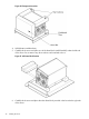
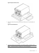
1. Cut and remove the polystrap bands securing the HP server to the pallet.
2. Lift the carton top from the cardboard tray resting on the pallet.
3. Remove the bezel kit carton and the top cushions from the pallet.
Wheel Kit Installation 41