
HP Integrity rx7640 and HP 9000 rp7440 Servers User Service Guide


The current power grid configuration is: Single grid
Power grid configuration preference.
1. Single grid
2. Dual grid
Select Option:
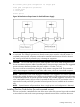
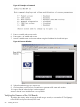
Figure 36 Distribution of Input Power for Each Bulk Power Supply
WARNING! Voltage is present at various locations within the server whenever a power source
is connected. This voltage is present even when the main power switch is in the off position. To
completely remove power, all power cords must be removed from the server. Failure to observe
this warning could result in personal injury or damage to equipment.
CAUTION: Do not route data and power cables together in the same cable management arm.
Do not route data and power cables in parallel paths in close proximity to each other. The suggested
minimum distance between the data and power cables is 3 inches (7.62 cm).
The power cord has current flowing through it, which creates a magnetic field. The potential to
induce electromagnetic interference in the data cables exists, which can cause data corruption.
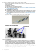
NOTE: Label the AC power cords during the installation. One suggestion is to use tie wraps that
have the flag molded into the tie wrap. The flag can be labeled using the appropriate two characters
to represent the particular AC power input (for example, A0). Another suggestion would be to use
color coded plastic bands. Use one color to represent the first pair A0/A1 and another color to
represent the second pair B0/B1 (provided a second power source is available at the customer
site).
NOTE: System firmware will prevent boot when a single power cord configuration is detected.
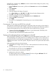
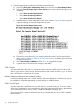
Installing The Line Cord Anchor (for rack mounted servers)
The line cord anchor is attached to the rear of the server when rack mounted. It provides a method
to secure the line cords to the server preventing accidental removal of the cords from the server.
Cabling and Power Up 61