
HP Integrity rx8620 Server User Service Guide
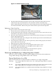

NOTE: The new CPU power pod is slightly hinged. Ensure that the CPU assembly is level
prior to lowering it onto the cell board.
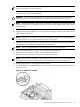
8. Using a 2.5 mm hex driver through the peep hole, turn the ZIF socket lock/unlock screw
one half turn to lock the CPU into place.
CAUTION: Do not exceed one half turn clockwise when locking the CPU into the ZIF
socket. Damage to the ZIF socket will occur, requiring the cell board to be replaced.
NOTE: Ensure that the ZIF socket is fully locked. Use a 2.5mm hex wrench to lock the ZIF
socket. Check that the CPU module housing is level and shifts slightly right when locking
the ZIF socket.
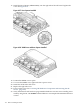
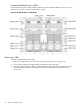
9. Push the load sequencer away from the fan.
10. Tighten the four CPU module screws in an X pattern, turning each screw two to three turns,
until all screws are secure.
NOTE: The processor screws do not need to be torqued. The processor will be properly
secured when the screws reach the bottom on the socket frame.
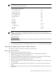
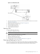
11. Tighten the two power pod screws, turning each two to three turns until secured. Ensure
that the entire CPU module is seated level in the cell board.
NOTE: Do not overtighten the screws. Damage can occur to the cell board.
12. Connect the Turbocooler fan cable to the connector on the cell board.
13. Route the power cable, left or right, to the cell board connector.
14. Reconnect the CPU power pod cable to the cell board connector.
NOTE: Due to space constraints, it may be necessary to use a tool to assist with inserting
CPU 0 and CPU2 power pod and Turbocooler cables into the cell board connectors.
15. Install remaining CPUs, keeping load order in mind.
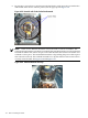
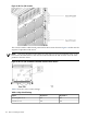
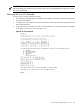
16. Install the VRM Cover (AB388-00002), onto the left side of the cell board. Tighten the screw.
See Figure 6-36.
Figure 6-36 VRM Cover Installed
Removing and Replacing a Central Processing Unit 151