
HP Integrity rx8620 Server User Service Guide
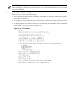

NOTE: Firmware must be updated to support the new processors. Below is an example
of minimum Firmware Version 4.0.
PROGRAMMABLE HARDWARE
1.002System Backplane GPM
1.002System Backplane FM
1.002System Backplane OSP
2.000PCI-X Backplane LPM
1.000PCI-X Backplane HS
2.008Core IO
1.002Cell LPM
1.009Cell PDHC
FIRMWARE:
A.007.002Core IO MP
1.012Event Dictionary
A.003.024Cell PDHC
3.066Cell SFW
NOTE: If the firmware or programmable hardware versions are not at or above the
minimum versions, go to the following website to obtain the latest Firmware Release Notice
and firmware patches.
External web site :
http://itrc.hp.com
The Firmware Update Release notice is included in the download bundle and includes the
upgrade instructions.
24. Power up the nPartition. See Appendix E (page 203).
25. To verify proper operation of the cell board, use the info cpu command from the EFI Shell.
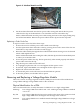
Removing and Replacing a Processor Turbo-Cooler Fan
The processor turbo-cooler fans are located on the cell boards.
Removing a Turbo-Cooler Fan
To remove a turbo-cooler fan, follow these steps:
1. Prepare an ESD safe work surface large enough to accommodate the cell board.
2. Identify the partition and cell to be removed.
3. Power off the nPartition and remove the cell with the fan to be replaced by following the
instructions in “Removing and Replacing a Cell Board” (page 120).
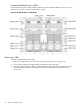
4. Place the cell board on the ESD safe work surface.
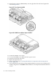
5. If necessary, loosen the four captive screws that secure the DIMM cover, remove the cover
and set it aside.
6. If so equipped, loosen the captive screws on the CPU cover, remove the cover and set it
aside.
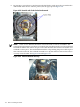
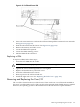
7. Identify the CPU turbo-cooler fan to be removed and unplug the fan power cord from the
cell board.
Removing and Replacing a Central Processing Unit 153