
HP Integrity rx8620 Server User Service Guide

1. Isolate the failing BPS. Table 6-8 defines the states of the single multicolored LED on the
BPS.
Table 6-8 BPS LED definitions
DescriptionLED State
BPS in standby state and no faults or warningsBlink Green
BPS in run state (48 volt output enabled) and no faults or warningsGreen
BPS in standby or run state and warnings present but no faultsBlink Yellow
BPS in standby state and recoverable faults present but no non-recoverable faultsYellow
BPS state may be unknown, non-recoverable faults presentBlink RED
This LED state is not usedRed
BPS fault or failure (unless AC power is not connected to server)Off
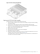
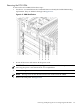
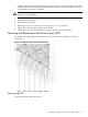
2. Remove the front bezel.
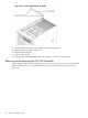
3. Depress the release latch on the upper front center portion of the BPS.
4. Slide the BPS forward using the handle to remove it from the chassis.
Figure 6-67 BPS Detail
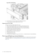
Replacing the BPS
To replace the BPS, follow these steps:
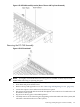
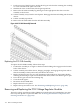
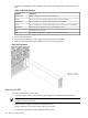
1. Grip the handle with one hand while supporting the rear of BPS in the other hand.
NOTE: The BPS easily slides into the chassis; however, a slow, firm pressure is needed to
properly seat the connection.
2. Slide the power supply into the slot until fully seated.
When seated, the release latch clicks and locks into place.
3. Note status of the BPS LED. The LED should be green.
180 Removal and Replacement