
HP Integrity rx8620 Server User Service Guide

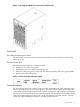
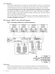

Figure 1-2 HP Integrity rx8620 Server (front view without bezel)
Front Panel
Front Panel Indicators and Controls
The front panel, located on the front of the server, includes a power switch. See “Front Panel
LEDs” (page 82).
Enclosure Status LEDs
The following status LEDs are on the front panel:
• Standby power status LED (green)
• Management processor (MP) status LED (green)
• Enclosure status run (green), fault (red), and attention (yellow), and power (green) LEDs
• Remote port status LED (green)
Figure 1-3 Front Panel LEDs and Power Switch
System Backplane
The server backplane board contains a pair of crossbar chips (XBC), the clock generation logic,
the reset generation logic, some power regulators, and two local bus adapter (LBA) chips that
create internal PCI buses for communicating with the core I/O cards. The backplane also contains
connectors for attaching the cell boards, PCI-X backplane, management processor (MP) core I/O
cards, SCSI cables, bulk power, chassis fans, front panel display, intrusion switches, external
system bus adaptor (SBA) link connectors, and the system scan card.
Introduction 19