
HP Integrity rx8620 Server User Service Guide
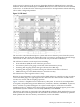
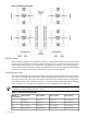
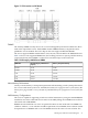
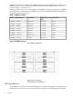
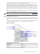
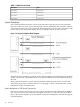
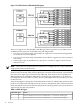
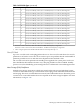
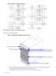

Table 1-5 Hard Disk Drive Path
PathHard Drive
0/0/0/2/0.6.0Slot 0 Drive
0/0/0/3/0.6.0Slot 1 Drive
1/0/0/2/0.6.0Slot 2 Drive
1/0/0/3/0.6.0Slot 3 Drive
System Backplane
The system backplane houses the system clock generation logic, the system reset generation
logic, DC-to-DC converters, power monitor logic, and two LBA link-to-PCI converter ASICs. It
is the point of connection for the cell boards, PCI-X backplane, core I/O cards, SCSI cables, bulk
power, chassis fans, front panel display, intrusion switches, and the system scan card.
Figure 1-10 System Backplane Block Diagram
The LBA PCI bus controllers are placed on the system backplane to facilitate hot-plug capability
for the core I/O cards. The partition for the core I/O card must be shut down before removing
the card.
Having the SCSI connectors on the system backplane enables hot-plug for the core I/O card
without having to remove cables in the process. Hot-plug circuitry is located near the system
backplane/core I/O card mating area.
System Backplane to Cell Board Connectivity
Four sets of vertical connectors serve as the point of connection for the cell boards. In addition,
two vertical connectors per cell board carry signals from the CC on the cell board to the SBA
chip on the PCI-X backplane, or an external I/O chassis PCI-X backplane, and back through the
system backplane.
26 Overview