
HP Integrity rx8620 Server User Service Guide


handles and PCI towel bars from the accessory kit A6093-04046. The towel bars and handles are
the same part. See service note A6093A-11.
There are several documents written to help with rack mounting the server. This list is intended
to guide the HP Installation Specialist to the documentation that has been written by the Rack
Solutions team.
Rack System/E
Detailed rack information for the rack system/E covers the following topics:
• Safety and Regulatory Information
• Description of the Standard Racks and Physical Specifications
• Installation Guidelines
• Procedures
Rack System/E Stabilizer Feet
The stabilizer installation guide for the rack system/E covers the following topics:
• How to Install the Stabilizers
• Moving the Rack
HP J1528A Rack Integration Kit
The rack integration kit information covers installing the following products:
• Ballast Kit (J1479A)
• Anti-Tip Stabilizer Kit (A5540A)
• Slide Rails
• CMA (Cable Management Arm)
• Interlock Device Assembly
This installation guide provides a complete parts list of the hardware and tools required to
perform the installation of the products mentioned. Installation of the products is illustrated in
this guide.
Manual Lifting
Use this procedure only if no HP approved lift is available.
This procedure should only be performed by four qualified HP Service Personnel utilizing proper
lifting techniques and procedures.
System damage can occur through improper removal and re-installation of devices. This task
must be performed by trained personnel only. Instructions for removing and re-installing these
components can be found in Chapter 6 (page 105).
CAUTION: Observe all ESD safety precautions before attempting this procedure. Failure to
follow ESD safety precautions can result in damage to the server.
To manually lift the server, follow these steps:
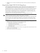
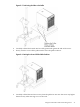
1. Reduce the weight by removing all bulk power supplies and cell boards.
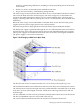
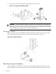
2. Locate the four (4) positioning handles on the sides of the system. They are color coded blue
and located close to each base corner of the unit.
3. Ensure the vertical support brackets are in the down position so they rest on the slides when
the server is lowered to the rack slides. There are two brackets on each side of the server
chassis.
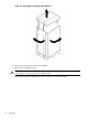
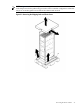
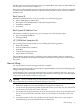
4. Unfold the handles so they are extended out from the unit. The server is now ready for
manual lifting by the four qualified HP Service Personnel.
Manual Lifting 37