
HP Integrity rx8620 Server User Service Guide
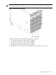
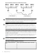
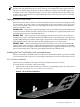
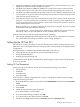
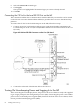
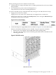
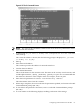
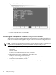

Figure 4-6 Distribution of Input Power for Each Bulk Power Supply
WARNING! Voltage is present at various locations within the server whenever a power source
is connected. This voltage is present even when the main power switch is in the off position. To
completely remove power, you must remove all power cords from the server. Failure to can
could result in personal injury or damage to equipment.
CAUTION: Do not route data and power cables together in the same cable management arm.
Do not route data and power cables in parallel paths in close proximity to each other. The
suggested minimum distance that the data and power cables should be apart is 3 inches (7.62
cm).
The power cord has current flowing through it, which creates a magnetic field. The potential to
induce electromagnetic interference in the data cables exist, which can cause data corruption.
The server can accommodate a total of six BPSs. N+1 BPS capability describes the server having
adequate BPSs plus one additional module installed. If one BPS fails, adequate power will still
be supplied to the cell board(s) to keep the server partition(s) operational. Replace the failed BPS
promptly to restore N+1 functionality.
A minimum of two BPS are required to bring up a single cell board installed in the server. This
minimum configuration is not N+1 capable. For BPS-to-cell-board N+1 configurations, see
Table 4-2.
IMPORTANT: The minimum supported N+1 BPS configuration for one cell board must have
BPS slots 0, 1, and 3 populated. When selecting a single power source, the power cords are
connected into A0 and A1.
Table 4-2 BPS to Cell Board Configuration to Achieve N+1
Number of Operational BPS Installed to Achieve N+1 FunctionalityNumber of Cell Boards Installed in the
Server
31
42
53
64
62 Cabling and Power Up